background image

45

PERIODIC SERVICE

ENGLISH

B

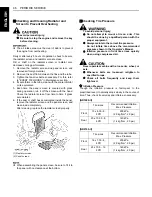
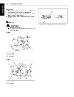
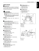
Checking Amount of Fuel and Refueling

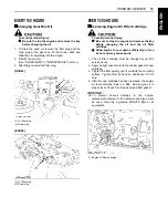
To avoid personal injury:

A

Handle fuel carefully. If the engine is running,
do not fill the fuel tank. If engine is hot, let
engine cool several minutes before adding fuel.
Do not smoke while filling the fuel tank or
servicing the fuel system. Fill fuel tank only to
bottom of filler neck.

Check the fuel level. Take care that the fuel tank does not
become empty.

A

Use Diesel Fuel Only

1. Use No.2 diesel fuel.
2. Use No.1 diesel fuel if the temperature is below -10

(14

).

3. Always use a strainer when refueling to prevent fuel

injection pump contamination.

A

No.2-D is a distillate fuel of lower volatility for engines
in industrial and heavy mobile service. 
(SAE J313 JUN87) 
Grade of Diesel Fuel Oil according to ASTM D975

Fuel tank capacity

18 L (4.8 U.S.gals.)

Flash point 

Water and 

Sediment, 

volume 

%

Carbon 

Residue on, 

10 percent 
Residuum,

%

Ash, weight 

%

Min

Max

Max

Max

52

0.05

0.35

0.01

Distillation 

Temperatures 


 90% Point

Viscosity 

Kinematics 

cSt or mm /s 

at 40

Viscosity 

Saybolt, SUS 

at 100

Min

Max

Min

Max

Min

Max

282

338

1.9

4.1

32.6

40.1

Sulfur, weight 

%

Copper strip 

Corrosion

Cetane 

Number

Max

Max

Min

0.50

No.3

40

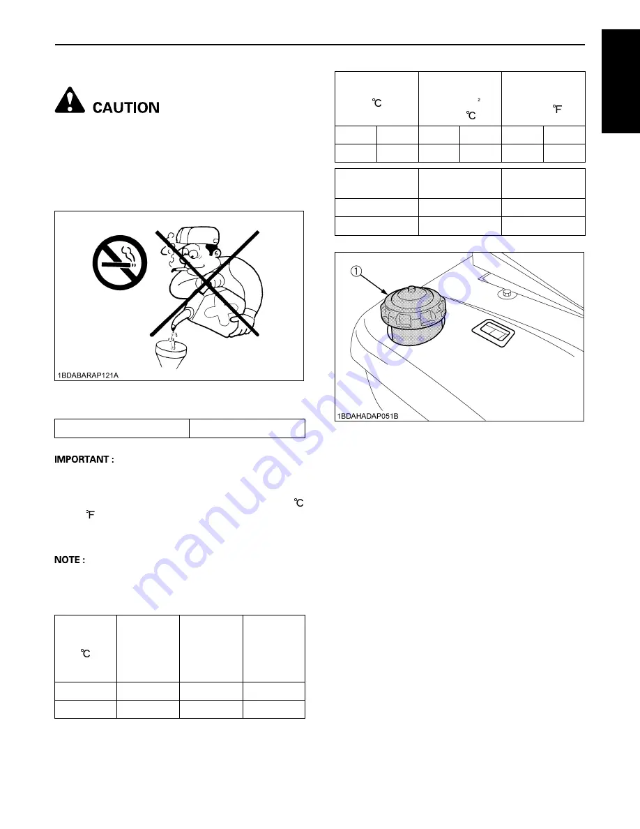
(1) Fuel port

Summary of Contents for GR1600-II

Page 1: ...0 II OPERATORÕS MANUAL KUBOTA RIDING MOWER MANUEL DE LÕUTILISATEUR TONDEUSE AUTOPORTEE KUBOTA BEDIENUNGSANLEITUNG KUBOTA AUFSITZMAHER 1BDAHAGAP0360 G R 1 6 0 0 II G R 2 1 0 0 II Code No N o de code K1254 7121 3 Code Nr PRINTED IN U S A IMPRIME AU U S A DRUCK U S A ...

Page 2: ...ENGLISH MODELS GR1600 II GR2100 II OPERATOR S MANUAL RIDING MOWER 1BDAHAGAP0360 ...

Page 3: ... symbols are shown below with an indication of their meaning 3 Safety Alert Symbol R Diesel Fuel Brake Parking Brake c Engine Stop Preheat v Engine Run Starter Control i Power Take Off Clutch Control Off Position u Power Take Off Clutch Control On Position Cutting Height Mower Lowered position Mower Raised position 9 9 9 9 9 Headlight Headlight ON f f f f f Headlight OFF j Fast k Slow Engine Speed...

Page 4: ...utors and dealers will have the most up to date information Please do not hesitate to consult them 3 SAFETY FIRST This symbol the industry s Safety Alert Symbol is used throughout this manual and on labels on the machine itself to warn of the possibility of personal injury Read these instructions carefully It is essential that you read the instructions and safety regulations before you attempt to ...

Page 5: ...FRANÇAIS MODELES GR1600 II GR2100 II TONDEUSE AUTOPORTEE 1BDAHAGAP0360 ...

Page 6: ... force Type permanent antigel au glycol éthylène Tours par minute Société des ingénieurs automobiles SYMBOLES UNIVERSELS Employés comme guide lors de l utilisation de votre tondeuse des symboles universels variés ont été apposés sur les contrôles et les instruments Ces symboles et leur significations sont montrés ci dessous 9 9 9 9 9 Eclairage Phares allumés f Phares éteints j Rapide k Lente Comma...

Page 7: ...t des informations les plus récentes N hésitez pas à les consulter 3 SYMBOLE DE DANGER Ce symbole est celui utilisé dans l industrie pour indiquer un danger Il est utilisé pour attirer votre attention sur des éléments ou des opérations qui pourraient être dangereux pour vous mêmes ou d autres utilisateurs de cette machine Lisez donc attentivement les consignes qu il signale Il est essentiel que vo...

Page 8: ...DEUTSCH MODELLE GR1600 II GR2100 II AUFSITZMAHER 1BDAHAGAP0360 ...

Page 9: ...chfolgend mit ihren entsprechenden Beschreibungen aufgeführt 9 9 9 9 9 Scheinwerfer Scheinwerfer EIN f f f f f Scheinwerfer AUS j Schnell k Langsam Gashebel g Batterie l Öldruck z Kühlflüssigkeitstemperatur Grasauffangbehälter Öffnen Angezogener Hebel Grasauffangbehälter Kippen Grasauffangbehälter Schließen Voller Grasauffangbehälter 3 Sicherheits Warnsymbol R Diesel Kraftstoff Bremse Parkbremse c...

Page 10: ...zu beachten damit es nicht zu Beschädigungen von Traktor und Anbaugeräten kommen kann HINWEIS Hinter diesem Zeichen finden Sie wichtige Informationen 3 DIE SICHERHEIT IST OBERSTES GESETZ Nun sind Sie der stolze Besitzer eines KUBOTA ZERO TURN MÄHERS Dieser Mäher ist ein Produkt der KUBOTA Qualitätstechnik und fertigung Er ist aus h o c h w e r t i g e n M a t e r i a l i e n u n d u n t e r e i n ...

Page 11: ... und Konstruktion dieser Machine entsprechen den erforderlichen grundlegenden Sicherheits und Gesundheitsanforderungen der Richtlinien 98 37 EG 2000 14 EG ANNEX VI und 89 336 EWG Cette machine est conforme aux exigences essentielles de sécurité et de santé selon la Directive EC 98 37 CE et de la Directive EC 2000 14 CE ANNEX VI et satisfait aussi à la compatibilité électromagnétique de la directiv...

Page 12: ......

Page 13: ......

Page 14: ...ontainer 12 OPERATING THE ENGINE 14 STARTING THE ENGINE 14 Key Switch 15 Cold Weather Starting 16 Block Heater Option 16 STOPPING THE ENGINE 16 WARMING UP 16 Warm up and Transmission Oil in the Low Temperature Range 16 JUMP STARTING 17 OPERATING THE MACHINE 18 OPERATING NEW MACHINE 18 Changing Lubricating Oil for New Machines 18 Engine Break in 18 Machine Break in 18 STARTING 19 Seat 19 Head Light...

Page 15: ... MATERIAL 33 Checking 33 Replacing 34 FRONT QUICK CLEAN LEVER 35 CLEANING 36 CLEANING WITH WATER 36 CLEANING THE GRASS CATCHING CONTAINER 36 CLEANING THE MOWING SYSTEM 36 CLEANING THE MOWING SYSTEM USING HOSE 36 TIRE AND WHEELS 37 TIRES 37 Inflation Pressure 37 WHEELS 38 MAINTENANCE 39 SERVICE INTERVALS 39 LUBRICANTS 41 PERIODIC SERVICE 43 HOW TO OPEN THE HOOD 43 DAILY CHECK 43 Checking Engine Oil...

Page 16: ...Checking Hydraulic Hose 63 Adjusting Front Axle Pivot 64 Checking Intake Air Line 64 EVERY 400 HOURS 64 Replacing Fuel Filter 64 EVERY 1500 HOURS 64 Checking Fuel Injection Nozzle Injection Pressure 64 EVERY 3000 HOURS 64 Checking Injection Pump 64 EVERY 1 YEAR 64 Replacing Air Cleaner Element 64 Flush Cooling System and Changing Coolant 64 Anti freeze 65 EVERY 2 YEARS 66 Replacing Hydraulic Hose ...

Page 17: ...CONTENTS ENGLISH ENGINE TROUBLESHOOTING 75 BATTERY TROUBLESHOOTING 75 MACHINE TROUBLESHOOTING 76 MOWER TROUBLESHOOTING 77 GRASS CATCHER TROUBLESHOOTING 78 OPTION 79 ...

Page 18: ...lace Replace all missing or damaged items for your safety 12 Never allow any bystanders around or near machine during operation Be sure the area is clear of other people before mowing Stop machine if anyone enters the area 13 Before allowing other people to use your machine explain proper operation to them and have them read this manual before operation 14 Never allow passengers or non qualified o...

Page 19: ...r traffic when operating the mower and grass catcher near public roads or highways 20 Do not operate where machine could tip or slip Do not operate near ditches holes embankments or other terrain which may collapse under the machine s weight The risk of machine tip over is increased when the ground is loose or wet 21 Raise and dump collected leaves or grass clippings ONLY while sitting on the oper...

Page 20: ...h safe machine operation 5 Never allow children to operate the machine even under adult supervision Local regulation can restrict the age of the operator 6 Use extra care when approaching blind corners shrubs trees or other obstructions that might hide children from sight C Operators age 60 years and above Data indicates that operators age 60 years and above are involved in a large percentage of m...

Page 21: ...t and keep equipment in good condition On multi bladed mowers take care as rotating one blade can cause other blades to rotate 12 Do not smoke when working around the battery Keep all sparks and flames away from battery The battery presents an explosion hazard because it gives off hydrogen and oxygen especially when recharging 13 Before JUMP STARTING a dead battery read and follow all of the instr...

Page 22: ...ye protection If injured by escaping fluid see a medical doctor at once Serious infection or reaction will result if proper medical treatment is not administered immediately This fluid can produce gangrene or severe allergic reaction 28 Waste products such as used oil fuel hydraulic fluid and batteries can harm the environment people pets and wildlife Please dispose of properly 29 Do not use bever...

Page 23: ... fumes may ignite Allow the engine to cool before storing 4 To avoid the danger of exhaust fume poisoning do not operate the engine in a closed building without adequate ventilation 5 To reduce fire hazards clean the machine thoroughly before storage Dry grass and leaves around the engine and mufflers may ignite 6 Moisture content in most grasses can damage the mower and grass catcher if these com...

Page 24: ...7 SAFE OPERATION ENGLISH 8 DANGER WARNING AND CAUTION LABELS ...

Page 25: ...SAFE OPERATION 8 ENGLISH ...

Page 26: ...9 SAFE OPERATION ENGLISH ...

Page 27: ...nger warning and caution labels with new labels from your local KUBOTA Dealer 4 If a component with danger warning and caution label s affixed is replaced with new parts make sure new label s is are attached in the same location s as the replaced component 5 Mount new danger warning and caution labels by applying on a clean dry surface and pressing any bubbles to outside edge 9 CARE OF DANGER WARN...

Page 28: ...nts to help you get the most value from it When in need of parts or major service be sure to see your KUBOTA Dealer When in need of parts be prepared to give your dealer the machine engine and mower serial numbers Locate the serial numbers now and record them in the space provided RCK42 RCK48 Type Serial No Machine Engine Mower Date of Purchase Name of Dealer To be filled in by purchaser 1 Machine...

Page 29: ... L 1 9 2 1 Hydrostatic transmission oil L 2 8 3 3 Machine PTO Shaft drive PTO clutch Mechanical Wet Multi Discs PTO brake Wet Multi Discs Tires Front 15 x 6 00 6 16 x 7 50 8 Rear 20 x 10 0 8 23 x 10 50 12 Steering type Manual Full hydraulic power steering Glide steer Brake Internal expanding brake Travel speed control Foot pedal Transmission Hydrostatic Traveling speeds Forward km h 0 to 10 Revers...

Page 30: ...9 Cutting height mm 25 to 102 Adjustment of cutting height Dial gauge Mounting method Quick joint Parallel linkage Weight Approx kg 75 80 Dimensions Total length mm 965 914 Total width mm 1110 1270 Total height mm 295 305 Discharge direction Rear Gear box oil L 0 33 0 4 Model GCK370GR II GCK450GR II Grass catcher Container Capacity L 370 450 Weight Approx kg 40 50 ...

Page 31: ...or which are not recommended for use with the KUBOTA Machine may result in malfunctions or failures of the machine damage to other property and injury to the operator or others Any malfunctions or failures of the machine resulting from use with improper implements are not covered by the warranty Maximum axle loading weight MODEL Front axle Wf Rear axle Wr Total gross weight GR1600 II 250 kg 450 kg...

Page 32: ...ensates for weight transferred to the rear wheels by the draft of towed implements through the hitch Add additional front ballast if necessary for stability and safety during transport of heavy rear mounted equipment Front end ballast may not always maintain the required stability if the machine is driven too fast over rough ground with heavy rear mounted equipment in the raised position Use care ...

Page 33: ...Throttle lever 21 4 Parking brake pedal 14 5 PTO lever 30 6 Hour meter 23 7 Key switch 15 8 Brake pedal 14 9 Speed control pedal 21 10 Mower lift lever GR1600 II 20 11 Hydraulic lift lever GR2100 II 20 12 Front quick clean lever 32 1 Grass container lift lever 32 2 Top cover lock lever 12 3 Rear quick clean lever 35 ...

Page 34: ...lever and lock in the raised position GR2100 II Pull the hydraulic lift lever to raise rear links 4 Adjust the height control dial to 1 Slide the mower deck under the machine Insert the container discharge duct between the mower duct and the lift link so that neither the container discharge duct the mower duct nor the lift link may interfere one another RCK42GR II RCK48GR II A Make sure that the m...

Page 35: ... Attach the front links to the front roller brackets A Adjust the length L of the front link See ADJUSTING THE PARALLEL LINKAGE in MOWER MOUNTING section 8 Pull the lever fulcrum fixing pin and turn it counter clockwise to lock 9 Hook and raise the front link with the link fixing lever and then lay the link fixing lever onto the front bracket of the machine 1 Mower lift lever 1 Hydraulic lift leve...

Page 36: ... of the universal joint Push the universal joint into the PTO shaft until the coupler locks Tug the universal joint backward and forward to make sure it is locked securely A Finally pull the universal joint to check if it is tight in position 1 Link fixing lever 2 Lever fulcrum fixing pin 3 Front link 4 Front bracket 1 Universal joint 2 Coupler A TUG ...

Page 37: ...p before making adjustments A Blades may be sharp When you handle blades wear heavy gloves or wrap end of blade with a rag 1 Park the machine on a level surface 2 Tire inflation pressure must be correct See TIRE AND WHEELS section 3 GR1600 II Raise the mower lift lever to the top position GR2100 II Raise the hydraulic lift lever to the top position 4 Turn the cutting height control dial to adjust ...

Page 38: ... the highest position Make sure that the stopper is in contact with the underside of the frame To adjust 1 Lift the mower to the highest position 2 Loosen the lock nut and adjust the stopper so that the bolt head is in contact with the underside of the frame 3 Lower the mower deck 4 Turn the stopper counterclockwise a half turn and then secure the lock nut DISMOUNTING THE MOWER DECK For dismountin...

Page 39: ...r to pull the top cover lock lever 3 Place the bottom of the grass container lift lever to the LEVER LOCK position 4 Hook the container to the frame shafts with the container rear edge inclined a little bit upward 5 Lock the container by inserting the grass container lift lever between 2 lock plates 1 Top cover 2 Top cover lock lever 1 Grass container lift lever A LEVER LOCK position 1 Container L...

Page 40: ...13 GRASS CATCHER MOUNTING ENGLISH 6 Close the top cover by pushing it to the frame 1 Top cover A PUSH ...

Page 41: ... the ground Start the engine only from the operator s seat STARTING THE ENGINE To apply the parking brake Depress the brake pedal firmly with your right foot and the parking brake pedal simultaneously with your left foot Then release the brake pedal while holding the parking brake pedal down To release the parking brake Depress the brake pedal and release slowly 1 Sit on the operator s seat 2 Appl...

Page 42: ... lever 1 2 way forward 1 Throttle lever FAST SLOW 5 Insert the key into the key switch and turn clockwise one notch Make sure the easy checker lights are ON OFF The position where the key can be inserted into or removed from the key switch When the key is turned to this position the engine shuts off ON The engine is running PREHEAT The super glow plug is heated START Depress the brake pedal fully ...

Page 43: ...his warm up period trouble such as seizure breakage or premature wear may develop BWarm up and Transmission Oil in the Low Temperature Range Hydraulic oil serves as transmission fluid In cold weather the oil may be cold with increased viscosity This can cause delayed oil circulation or abnormally low hydraulic pressure for some time after engine start up This in turn can result in trouble in the h...

Page 44: ...ive red or pos terminal of the dead battery and clamp the other end of the same cable to the positive red or pos terminal of the helper battery 7 Clamp the other cable to the negative black or neg terminal of the helper battery 8 Clamp the other end to the engine block or frame of the disabled machine as far from the dead battery as possible 9 Start the helper vehicle and let its engine run for a ...

Page 45: ...E section BMachine Break in After the first 200 hours of operation change the transmission fluid After the first 50 hours of operation change the oil filter cartridge See EVERY 200 HOURS in PERIODIC SERVICE section To avoid personal injury A Do not allow any person other than the driver to ride on the machine A Do not drive the machine close to the edges of ditches or banks which may collapse unde...

Page 46: ...he machine The operator s seat position can be adjusted forward and backward by 175 mm 6 9 in range by pulling the seat sliding lever A After adjusting the operator s seat be sure to check that the seat is properly locked BHead Light Switch A Head lights ON B Head lights OFF 1 Adjusting the operator s position 1 Seat sliding lever 2 Selecting Light Switch Positions 1 Head light switch 1 Head light...

Page 47: ...r is used to raise and lower implement used with the machine ex Mower To lower implement push the lever FORWARD To raise it pull the lever BACKWARD A Do not operate until the engine is warmed up If operation is attempted when the engine is still cold the hydraulic system may be damaged A Do not operate at slow Engine rpm Move the throttle lever above 1 2 A If noises are heard when implement is lif...

Page 48: ... the speed control pedal with the toe of your right foot to move forward REVERSE Depress the speed control pedal with the heel of your right foot to move in reverse Depress the speed control pedal a little and you can drive slowly To increase travel speed depress the speed control pedal more until the desired speed is reached A When the parking brake is applied the speed control pedal is locked in...

Page 49: ...tor is not charging the battery the warning lamp in the Easy Checker TM will come on If this should happen during operation check the electrical charging system or consult your local KUBOTA Dealer Coolant temperature If this warning light comes on during operation take the actions according to Checking and Cleaning Radiator to Prevent Overheating Glow plug Indicator Pre heating Indicator When the ...

Page 50: ...RED in PERIODIC SERVICE section A Do not refuel over F Fill the tank only to the bottom of the filler neck in the fuel tank BHourmeter The hourmeter indicates in five digits the hours the machine has been used the last digit indicates 1 10 of an hour A As the hour meter works electrically it starts to work when the key switch is turned to ON regardless of the engine running or not 1 Fuel gauge E E...

Page 51: ... of the machine TRANSPORTING 1 Transport the machine on a trailer A Fasten the machine to the trailer A To prevent the hood from opening by wind while in transit it is necessary to either load the machine forward or use a suitable tie down for the hood 2 Do not attempt to tow this machine or damage to the transmission may result BDirections for Use of Power Steering GR2100 II 1 Power steering is a...

Page 52: ... tire speed differences small If the adjustment is not correct or some malfunction occurs in the system rear clutches are engaged all times and result in larger turn radius or turf damage In that case contact your Kubota dealer for checking BHitch Plate To install the hitch plate 1 Remove the grass container from the machine A This hitch plate can use only with the grass container or the discharge...

Page 53: ...OPERATING THE MACHINE 26 ENGLISH To remove the hitch plate 1 Reverse the above procedure 1 Hitch plate 2 Clevis pin 3 Snap pin ...

Page 54: ... grass to grow to 80 mm 3 in then cut off only the top inch 5 For best appearance grass should be cut in the afternoon or evening when it is free of moisture To avoid serious injury or death A Do not operate mower without Grass Catcher To avoid personal injury A Clear the work area of objects which might be picked up and thrown by blades A Keep bystanders and animals away from the mowing area A Be...

Page 55: ...e button and lowering the lever while holding in the release button This lowers the mower deck from the Transport position to the Operating position 6 Use the higher settings for mowing in a rough area or when mowing tall grass Lower settings should be used only for smooth lawns where short grass is desired RCK42 1 Mower lift lever 2 Cutting height control dial 1 Hydraulic lift lever 2 Cutting hei...

Page 56: ...etween rollers and the ground 1 25 1 1 6 mm 0 2 in 1 25 32 2 12 4 mm 0 5 in 1 5 38 19 0 mm 0 7 in 1 75 44 25 4 mm 1 0 in 2 0 50 2 19 0 mm 0 7 in 2 25 58 25 4 mm 1 0 in 2 5 64 3 19 0 mm 0 7 in 2 75 70 25 4 mm 1 0 in 3 0 76 3 31 8 mm 1 3 in 3 5 89 3 44 6 mm 1 8 in 4 0 102 3 57 4 mm 2 3 in 1 Cutting height 1 is a ground clearance of 6 mm 2 Cutting height 1 25 is a ground clearance of 12 4 mm 3 For cu...

Page 57: ...n Use the speed control pedal to select the desired mowing speed range 1 Control ground speed by using the speed control pedal of the machine A Keep the mower deck in the fully raised position when the mower is not engaged To avoid serious injury or death A Engine components can get extremely hot from operation To prevent severe burns do not touch these areas while the engine is running or immedia...

Page 58: ...container is filled After tall grasses have been mowed reset the mower to the desired height of cut and remow the area 4 Always mow at full engine throttle If the engine lugs down while mowing reduce riding mower ground speed C EASY Checker TM Full grass indicator If grass gets stuck up to the grass sensor set position this indicator lights up and the buzzer sounds If this lamp is on dump the gras...

Page 59: ... sure the dumping area is clear of all bystanders and pets before emptying grass clippings or leaves from the container To empty 1 Disengage the PTO lever 2 Pull up the grass container lift lever completely and then rotate it forward to dump the grass 3 Operate the rear quick clean lever several times to dump the grass in the duct A If needed operate the front quick clean lever See FRONT QUICK LEV...

Page 60: ...stop the engine before checking the grass container net condition A The grass container net material is subject to deterioration and wear Check it frequently Use only genuine replacement net from KUBOTA A Make sure all shields and guards are securely in place following all service cleaning or repair work The grass container net material should be checked daily 1 The net material is made of cloth a...

Page 61: ...astic cover from the container 3 Remove square neck bolts and nuts to remove the bottom plate 4 Then remove the container net from the frame 5 To attach new or cleaned net reverse the above procedures and be sure to install removed components 1 Handle 2 Flange nut 3 Black flange bolt 4 Cover 1 Bottom plate 2 Square neck bolt 3 Flange nut 1 New or cleaned net ...

Page 62: ...o operate 1 Park the machine on a level surface 2 Raise the mower to the highest position 3 Pull the PTO lever to the DISENGAGED position And allow the blades to stop before operating the lever 4 Pull the lever several times RCK42 RCK48 A To effectively discharge the grass be sure to pull the lever several times 1 Front quick clean lever 1 Front quick clean lever ...

Page 63: ... after cleaning A If the mower was used under very difficult conditions very wet grass mowing in a very low position it may be necessary to remove the cutting deck to clean it At the same time you should take the opportunity to check the condition of the blades belts and bolts and replace them if needed To avoid serious injury or death A Do not clean the mower deck without the Grass Catcher attach...

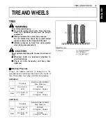
Page 64: ...ver bolts are loosened retighten to specified torque A Check all bolts frequently and keep them tightened BInflation Pressure Though the inflation pressure is factory set to the prescribed level it naturally drops slowly in the course of time Thus check it everyday and inflate as necessary GR1600 II GR2100 II Tire sizes Recommended Inflation Max Pressure Front 15 x 6 00 6 4PR 200 kPa 2 0 kgf cm 29...

Page 65: ... after travelling 200 m 200 yards changing directions several times A Wheels with beveled or tapered holes Use the tapered wheel bolt Front 1 Front tire assy 2 Axle 3 Plain washer 4 Cotter pin 5 Front wheel cap 1 Plain washer 2 Plain washer 3 Key 4 Rear axle 5 Rear tire 6 Plain washer 7 Retaining ring 8 Rear wheel cap 1 Bolt Front 108 5 to 130 2 N m 11 07 to 13 29 kgf m 80 to 96 ft lbs 1 Nut 2 Spr...

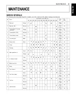
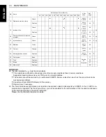
Page 66: ...very 200 Hr 61 5 Transmission strainer Clean every 200 Hr 60 6 Front axle pivot Adjust every 200 Hr 64 2 7 Safety device Check every 50 Hr 49 8 Oiling every 50 Hr 52 9 Greasing every 50 Hr 48 10 Mower gear box oil Check every 50 Hr 50 Change every 150 Hr 59 11 Air cleaner element Clean every 50 Hr 50 1 Replace every 1 year 64 12 Battery condition Check every 50 Hr 55 13 Brake Adjust every 100 Hr 5...

Page 67: ...lation As the engine owner you are responsible for the performance of the required maintenance on the engine according to the above instruction Please see the Warranty Statement in detail 18 Radiator hose and clamp Check every 200 Hr 62 Replace every 2 years 66 2 19 Intake air line Check every 200 Hr 64 Replace every 2 years 66 4 20 Fuel injection nozzle injection pressure Check every 1500 Hr 64 3...

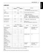
Page 68: ... 10W 40 Below 0 SAE10W SAE10W 30 or 10W 40 Transmission case 2 8 L 3 3 L KUBOTA UDT or SUPER UDT fluid 1 Front axle case 1 9 L Mower gear box 0 33 L 0 4 L SAE 90 gear oil API service classification more than GL 3 Greasing No of greasing points Capacity Type of grease GR1600 II GR2100 II Engine transmission universal joint 1 Until grease overflows Multipurpose Grease NLGI 2 OR NLGI 1 GC LB King Pin...

Page 69: ...used with a high sulfur fuel change the lubricating oil at shorter intervals A Lubricating oil recommended when a low sulfur or high sulfur fuel is employed A Transmission oil KUBOTA SUPER UDT 1 KUBOTA Original Transmission hydraulic fluid The oil used to lubricate the transmission is also used as hydraulic fluid To insure proper operation of the hydraulic system and complete lubrication of the tr...

Page 70: ...ortant to know the condition of the machine Check it before starting To avoid personal injury A Be sure to check and service the machine on a level surface with the engine shut off the key removed and the parking brake securely set No Check item Ref Page Walking around the machine 1 Tire pressure wear and damage 37 46 2 Oil and water leak 3 Engine oil level 44 4 Transmission fluid level 47 5 Coola...

Page 71: ...rand or viscosity oil from the previous one remove all of the old oil and oil filter Never mix two different types of oil 6 Use the proper Engine Oil SAE according to the ambient temperatures See LUBRICANTS in MAINTENANCE section Turning the key switch on 1 Performance of the easy checker light 22 Starting the engine 1 Color of the exhaust fumes 2 Safety start switch seat safety control and anothe...

Page 72: ... fuel if the temperature is below 10 14 3 Always use a strainer when refueling to prevent fuel injection pump contamination A No 2 D is a distillate fuel of lower volatility for engines in industrial and heavy mobile service SAE J313 JUN87 Grade of Diesel Fuel Oil according to ASTM D975 Fuel tank capacity 18 L 4 8 U S gals Flash point Water and Sediment volume Carbon Residue on 10 percent Residuum...

Page 73: ...creen and clean inside completely After cleaning replace the radiator screen properly A When assembling the panel screen be sure to fit it to the panel with no clearance at the bottom BChecking Tire Pressure To avoid personal injury A Do not attempt to mount a tire on a rim This should be done by a qualified person with the proper equipment A Always maintain the correct tire pressure Do not inflat...

Page 74: ...en cap slightly to the stop to relieve any excess pressure before removing cap completely Check the coolant level daily both the radiator and the recovery tank before starting engine 1 Remove the radiator cap and check to see that the coolant level is just below the fill port 2 Check to see that the coolant level is between the FULL and LOW marks of recovery tank 3 When the coolant level drops due...

Page 75: ...water and anti freeze to fill the radiator and the recovery tank A If water should leak consult your local KUBOTA Dealer BGreasing To avoid personal injury A Be sure to stop the engine and remove the key before greasing RCK42 RCK48 1 Spindle shaft 2 Tension arm 1 Spindle shaft 2 Tension arm 1 Mower universal joint Apply grease on the spline shaft ...

Page 76: ...3 Turn the key switch to the START position 4 The engine should not crank C Safety Start Control 2 1 Disengage the PTO lever 2 Release the brake pedal 3 Turn the key to the START position 4 The engine should not crank C Seat Safety Control 1 1 Run the engine at half throttle 2 Engage the PTO lever 3 Stand up DO NOT GET OFF THE MACHINE 4 Engine should shut off C Seat Safety Control 2 1 Run the engi...

Page 77: ... the arrow marks when reinstalling the air cleaner cover BChecking Gear Box Oil Level To avoid personal injury A Always stop the engine and remove the key before checking oil 1 Park the machine on a flat surface and lower the mower to the ground To check the oil level loosen the check plug and check to see that the oil level is just below the check plug port If the level is too low add new oil to ...

Page 78: ...e to stop the engine and remove the key before greasing Grease the following location 1 Engine transmission universal joint Apply grease on the spline shaft 1 Center pin GR2100 II 1 King pin LH RH 1 Support king pin LH RH 2 Glide steer bolt 1 Glide steer rear arm GR2100 II ...

Page 79: ...op the engine and remove the key before greasing Oil the following locations 1 Mower universal joint 1 Speed control shaft RH 1 Speed control shaft LH 1 Seat adjuster 1 Throttle cable 1 Around the hole of the mower link 2 Around the pin 3 Pivot of mower link 4 Pivot of liftarm ...

Page 80: ...53 PERIODIC SERVICE ENGLISH 1 Front link 1 Top cover lock lever 2 Frame shaft 1 Top cover 2 Arm bracket 1 Rear quick clean lever ...

Page 81: ...PERIODIC SERVICE 54 ENGLISH 1 PTO lever fulcrum 2 Hydraulic lift lever fulcrum 1 Link fulcrum 1 Glide steer cable LH RH ...

Page 82: ...vated hydrogen and oxygen gases in the battery are extremely explosive Keep open sparks and flames away from the battery at all times especially when charging the battery To avoid personal injury A When charging battery ensure that the vent caps are securely in place if equipped A When disconnecting the cables from the battery start with the negative terminal first When connecting the cables to th...

Page 83: ... the electrolyte to the proper level and store in a dry place out of direct sunlight 2 The battery self discharges while it is stored Recharge it once every three months in hot seasons and once every six months in cold seasons EVERY 100 HOURS BChanging Engine Oil To avoid personal injury A Be sure to stop the engine and remove the key before changing the oil A Allow engine to cool down sufficientl...

Page 84: ... rubber and ages regardless of service period 2 If the fuel line and clamps are found to be damaged or deteriorated replace them 3 Check fuel filter if it is clogged by debris or contaminated with water replace it A When the fuel line is disconnected for maintenance or repair close both ends of the fuel line with a piece of clean cloth or paper to prevent dust and dirt from entering In addition pa...

Page 85: ...personal injury A Be sure to stop the engine and remove the key before checking belt tension If the fan drive belt becomes loose the engine may overheat To adjust loosen bolts and move the dynamo outward to tighten the belt After adjustment securely tighten the bolts Moderate belt tension The belt should deflect approx 10 mm 0 39 in when the center of the belt is depressed with finger pressure of ...

Page 86: ... the oil and the oil filter cartridge A Allow engine to cool down sufficiently oil can be hot and may cause burns 1 The oil filter cartridge must be changed every 200 service hours 2 Apply a slight coat of oil onto the rubber gasket of new cartridge 3 Tighten the filter quickly until it contacts the mounting surface Tighten filter by hand an additional 1 2 turn only 4 After the new cartridge has b...

Page 87: ...r a few minutes stop it and check the oil level again add oil to the prescribed level A Check the oil level of the transmission case with the mower lifted up A Operate only at low RPM s immediately after changing the transmission fluid and filter cartridge Keep the engine at medium speed for a few minutes to insure proper lubrication of all parts so there is no damage to transmission A Do not enga...

Page 88: ...oosen the wing bolt and remove the filter cover Then remove the oil filter cartridge by using the filter wrench 4 Lightly tighten the screw A by using a screwdriver 5 Apply a slight coat of oil onto the cartridge gasket 6 Tighten the filter quickly until it contacts the mounting surface Tighten filter by hand an additional 1 2 turn only 7 Assemble the cover and mount the grass container 8 After th...

Page 89: ... 2 To drain the used oil remove the right and left drain plugs and filling plug at the front axle case and drain the oil completely into the oil pan 3 After draining reinstall the drain plugs 4 Remove the right and left breather plugs 5 Fill with the new oil up to the upper notch on the dipstick See LUBRICANTS in MAINTENANCE section A After ten minutes check the oil level again add oil to prescrib...

Page 90: ...wn sufficiently oil can be hot and may cause burns Check to see if hydraulic hoses are properly fixed every 200 hours of operation 1 Check to see that all lines and hose clamps are tight and not damaged 2 If hoses and clamps are found worn or damaged replace or repair them at once 1 Power steering hose RH 2 Power steering hose LH 1 Power steering hose RH 1 Power steering hose LH 1 Mower lift cylin...

Page 91: ...BChecking Fuel Injection Nozzle Injection Pressure Consult your local KUBOTA Dealer for this service EVERY 3000 HOURS BChecking Injection Pump Consult your local KUBOTA Dealer for this service EVERY 1 YEAR BReplacing Air Cleaner Element Change the element once a year BFlush Cooling System and Changing Coolant To avoid personal injury A Do not remove the radiator cap when the engine is hot Then loo...

Page 92: ...ces A Anti freeze is extremely flammable and explosive under certain conditions Keep fire and children away from anti freeze A When draining fluids from the engine place some container underneath the engine body A Do not pour waste onto the grounds down a drain or into any water source A Also observe the relevant environmental protection regulations when disposing of anti freeze If it freezes cool...

Page 93: ...ted anti freeze A When the coolant level drops due to evaporation add water only to keep the anti freeze mixing ratio less than 50 In case of leakage add anti freeze and water in the specified mixing ratio before filling in to the radiator EVERY 2 YEARS BReplacing Hydraulic Hose Replace hoses and hose clamps every 2 years or earlier if checked and found that hoses are swollen hardened or cracked B...

Page 94: ...ose hood BChecking and Replacing Blade To avoid personal injury A Be sure to stop the engine and remove the key A Blades may be sharp When you handle blades wear heavy gloves or wrap end of blade with a rag C Checking The blade cutting edges should be kept sharp at all times Sharpen the cutting edges if they resemble blade B Replace the blades if they appear similar to blade C FUSE NO ID LABEL CAP...

Page 95: ... and file along the original bevel until sharp 5 To check the blade for balance place a small rod through the center hole If the blade is not balanced file the heavy side of the blade until balance is achieved 6 To attach blades be sure to install the 2 cup washers between the blade and bolt head A Make sure that the cup washer is not flattened out or worn this may cause blade to slip excessively ...

Page 96: ...ECK 2 Remove the left and right hand shields from the mower deck 3 Clean around the pulleys to remove the belt from the pulleys Slip the belt over the top of the pulley 4 Remove both brackets which mount the gear box to the mower deck RCK42 Tighten each bolt and nut with following torque A Bolt M12 77 6 to 90 2 N m 8 0 to 9 2 kgf m A Bolt M10 and Nut M10 48 1 to 55 9 N m 4 9 to 5 7 kgf m 1 Spindle...

Page 97: ...ing torque A Reamer bolt M12 and Bolt M12 77 6 to 90 2 N m 8 0 to 9 2 kgf m 5 To install a new belt reverse the above procedure A When attaching the bracket tighten the reamer bolt first 1 Bolt 1 Left hand shields 2 Right hand shield 1 Belt 2 Gear box 1 RH belt 2 Tension pulley 3 LH belt 4 Left hand shield 5 Right hand shield 6 Left side pulley 7 Reamer bolt 8 Bolt ...

Page 98: ...hen the fuel filter or lines are removed 2 When tank is completely empty 3 After the machine has not been used for a long period of time C Bleeding procedure is as follows 1 Fill the fuel tank with fuel 2 Start the engine and run for about 30 seconds and then stop the engine ...

Page 99: ...f m 35 42 47 5 57 0 4 84 5 82 45 54 61 0 73 2 6 22 7 47 M10 ft lbs N m kgf m 35 5 41 2 48 1 55 8 4 9 5 7 44 9 52 1 60 8 70 5 6 2 7 2 7 16 ft lbs N m kgf m 56 66 75 9 89 5 7 74 9 12 75 90 101 7 122 10 37 12 44 M12 ft lbs N m kgf m 57 2 66 5 77 5 90 1 7 9 9 2 76 0 86 8 103 117 10 5 12 0 1 2 ft lbs N m kgf m 80 96 108 5 130 2 11 07 13 29 110 132 149 2 179 0 15 22 18 27 M14 ft lbs N m kgf m 91 2 108 1...

Page 100: ...13 0 15 2 14 1 1 1 17 8 20 6 19 2 1 4 1 9 2 1 2 0 0 1 17 5 20 3 18 9 1 4 23 5 27 5 25 5 2 0 2 4 2 8 2 6 0 2 M10 14 or 17 28 9 33 3 31 1 2 2 39 3 45 1 42 2 2 9 4 0 4 6 4 3 0 3 35 4 41 2 38 3 2 9 48 1 55 9 52 0 3 9 4 9 5 7 5 3 0 4 M12 17 or 19 46 3 53 5 49 9 3 6 62 8 72 6 67 7 4 9 6 4 7 4 6 9 0 5 57 1 66 5 61 8 4 7 77 6 90 2 83 9 6 3 8 0 9 2 8 6 0 6 M14 19 or 22 79 6 92 6 86 1 6 5 107 9 125 5 116 7 ...

Page 101: ...wo months in cold seasons 7 Drain fuel tank fuel lines 8 Store the machine where it is dry and sheltered from rain Cover the machine with a tarpaulin 9 Moisture content in most grasses can damage the mower and grass catcher if these components are not properly cleaned after use Make sure the mower and the grass catcher are clean and completely empty before storage 10 Jack the machine up and place ...

Page 102: ...or Black smoke is emitted from the muffler during operation power output is lowered A Air cleaner element clogged Bluish white smoke is emitted from the muffler during operation A Too much engine oil Engine will not idle A Fuel filter is clogged Engine overheats A Low coolant level A Loose or defective fan belt A Coolant flow route corroded If Check Starter does not function A Battery discharged A...

Page 103: ...Check Machine operation is not smooth A Hydrostatic transmission oil is low Machine does not move while engine is running A Parking brake is on A Transmission oil is insufficient Machine moves when speed control pedal is not depressed Engine is operated A Hydrostatic neutral system is not correctly adjusted ...

Page 104: ...er rollers not adjusted correctly Blades scalping grass A Cutting height too low A Blades speed too fast A Ridges in terrain A Rough or uneven terrain A Bent blade s A Low tire inflation A Anti scalp rollers not adjusted correctly Belt slipping A Belt tension incorrect A Mower deck plugged A Debris in pulleys A Worn belt Excessive vibration A Debris on mower deck or in pulleys A Damaged drive belt...

Page 105: ...ealer If Check Discharge duct plugged A Grass too wet A Grass too long A Cutting too low A Engine rpm low A Ground speed too fast A Grass container full A Grass container net clogged Dumped and undischarged clippings A Duct plugged A Grass container full A Mower deck plugged A Grass container net clogged ...

Page 106: ... is used when both discharging and scattering the grass clippings to the rear of the machine without collecting VIBRATION Model Engine Rated Speed Vibration 1 Arm Body GR1600 II 3300 rpm Below 2 6 m s Below 0 5 m s GR2100 II 3100 rpm 1 Arm Vibration evaluated based on ISO 5349 Body Vibration evaluated in field based on ISO 5008 ...

Reviews: