TRANSAXLE
GR1600EU, WSM
2-S24
(2) Transaxle Case
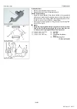
Disassembling PTO Clutch Assembly
1. Remove the PTO cover assembly (1) with the brake disc and
friction plate, PTO clutch assembly (3) and 24T gear (2) from
the transaxle case.
2. Remove the ball bearing (4) from the transaxle case.
3. Remove the 24T gear (2), PTO clutch assembly (3), brake disc
and friction plate (5) from PTO shaft (6).
4. While pressing the PTO clutch assembly (3), turn the clutch
case (7) clockwise. Then, separate the clutch case (7) and the
spline boss (12) with clutch disc and friction plate (13).
5. Remove the thrust needle bearing (8), thrust collar (9), collar
(10) and spring (11).
6. Remove the external snap ring (14), clutch disc and friction
plate (13) from the spline boss (12).
(When reassembling)
9Y1210595TXS0042US0
Tightening torque
PTO cover assembly
mounting screw
18 to 20 N·m
1.8 to 2.1 kgf·m
13 to 15 lbf·ft
(1) PTO Cover Assembly
(2) 24T Gear
(3) PTO Clutch Assembly
(4) Ball Bearing
(5) Brake Disc and Friction Plate
(6) PTO Shaft
(7) Clutch Case
(8) Thrust Needle Bearing
(9) Thrust Collar
(10) Collar
(11) Spring
(12) Spline Boss
(13) Clutch Disc and Friction Plate
(14) External Snap Ring
KiSC issued 11, 2013 A
Summary of Contents for GR1600EU
Page 1: ...GR1600EU WORKSHOP MANUAL KiSC issued 11 2013 A ...
Page 4: ...I INFORMATION KiSC issued 11 2013 A ...
Page 10: ...INFORMATION GR1600EU WSM I 5 9Y1210595INI0002US0 KiSC issued 11 2013 A ...
Page 11: ...INFORMATION GR1600EU WSM I 6 9Y1210595INI0003US0 KiSC issued 11 2013 A ...
Page 12: ...INFORMATION GR1600EU WSM I 7 9Y1210595INI0007US0 KiSC issued 11 2013 A ...
Page 16: ...INFORMATION GR1600EU WSM I 11 2 GR1600ID 9Y1210595INI0009US0 KiSC issued 11 2013 A ...
Page 17: ...G GENERAL KiSC issued 11 2013 A ...
Page 80: ...1 ENGINE KiSC issued 11 2013 A ...
Page 138: ...2 TRANSAXLE KiSC issued 11 2013 A ...
Page 194: ...3 BRAKES KiSC issued 11 2013 A ...
Page 195: ...CONTENTS 1 BRAKE MECHANISM 3 M1 MECHANISM KiSC issued 11 2013 A ...
Page 205: ...4 FRONT AXLE KiSC issued 11 2013 A ...
Page 213: ...5 STEERING KiSC issued 11 2013 A ...
Page 221: ...6 ELECTRICAL SYSTEM KiSC issued 11 2013 A ...
Page 223: ...ELECTRICAL SYSTEM GR1600EU WSM 6 M1 1 WIRING DIAGRAM 1 GR1600EU GR1600F KiSC issued 11 2013 A ...
Page 224: ...ELECTRICAL SYSTEM GR1600EU WSM 6 M2 2 GR1600ID KiSC issued 11 2013 A ...
Page 257: ...7 MOWER KiSC issued 11 2013 A ...


