ELECTRICAL SYSTEM
GR1600EU, WSM
6-S14
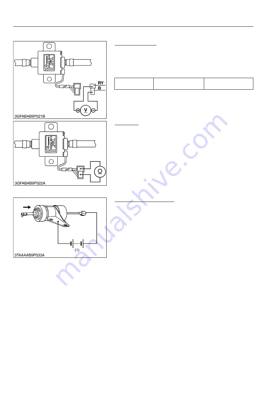
(7) Fuel Pump
Connector Voltage
1. Disconnect the
2P
connector from the fuel pump.
2. Turn the main switch key to the
"ON"
position, and measure the
voltage with a voltmeter between the connector terminals.
3. If the voltage differs from the battery voltage, the wiring harness
or main switch is faulty.
9Y1210595ELS0022US0
Fuel Pump
1. Disconnect the
2P
connector from the fuel pump.
2. Check the continuity between the connector terminals with an
ohmmeter.
3. If it does not conduct, the fuel pump is faulty.
9Y1210595ELS0023US0
(8) Engine Stop Solenoid
Engine Stop Solenoid Test
1. Disconnect the
1P
connector from the engine stop solenoid.
2. Remove the engine stop solenoid from the engine.
3. Connect the jumper leads from the battery positive terminal to
the
1P
connector, and from the battery negative terminal to the
engine stop solenoid body.
4. If the solenoid plunger is not attracted, the engine stop solenoid
is faulty.
9Y1210595ELS0024US0
Voltage
Between connector
terminals
Approx. battery voltage
(1) Battery (12 V)
KiSC issued 11, 2013 A
Summary of Contents for GR1600EU
Page 1: ...GR1600EU WORKSHOP MANUAL KiSC issued 11 2013 A ...
Page 4: ...I INFORMATION KiSC issued 11 2013 A ...
Page 10: ...INFORMATION GR1600EU WSM I 5 9Y1210595INI0002US0 KiSC issued 11 2013 A ...
Page 11: ...INFORMATION GR1600EU WSM I 6 9Y1210595INI0003US0 KiSC issued 11 2013 A ...
Page 12: ...INFORMATION GR1600EU WSM I 7 9Y1210595INI0007US0 KiSC issued 11 2013 A ...
Page 16: ...INFORMATION GR1600EU WSM I 11 2 GR1600ID 9Y1210595INI0009US0 KiSC issued 11 2013 A ...
Page 17: ...G GENERAL KiSC issued 11 2013 A ...
Page 80: ...1 ENGINE KiSC issued 11 2013 A ...
Page 138: ...2 TRANSAXLE KiSC issued 11 2013 A ...
Page 194: ...3 BRAKES KiSC issued 11 2013 A ...
Page 195: ...CONTENTS 1 BRAKE MECHANISM 3 M1 MECHANISM KiSC issued 11 2013 A ...
Page 205: ...4 FRONT AXLE KiSC issued 11 2013 A ...
Page 213: ...5 STEERING KiSC issued 11 2013 A ...
Page 221: ...6 ELECTRICAL SYSTEM KiSC issued 11 2013 A ...
Page 223: ...ELECTRICAL SYSTEM GR1600EU WSM 6 M1 1 WIRING DIAGRAM 1 GR1600EU GR1600F KiSC issued 11 2013 A ...
Page 224: ...ELECTRICAL SYSTEM GR1600EU WSM 6 M2 2 GR1600ID KiSC issued 11 2013 A ...
Page 257: ...7 MOWER KiSC issued 11 2013 A ...


