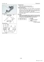
TRANSAXLE
GR1600EU, WSM
2-S16
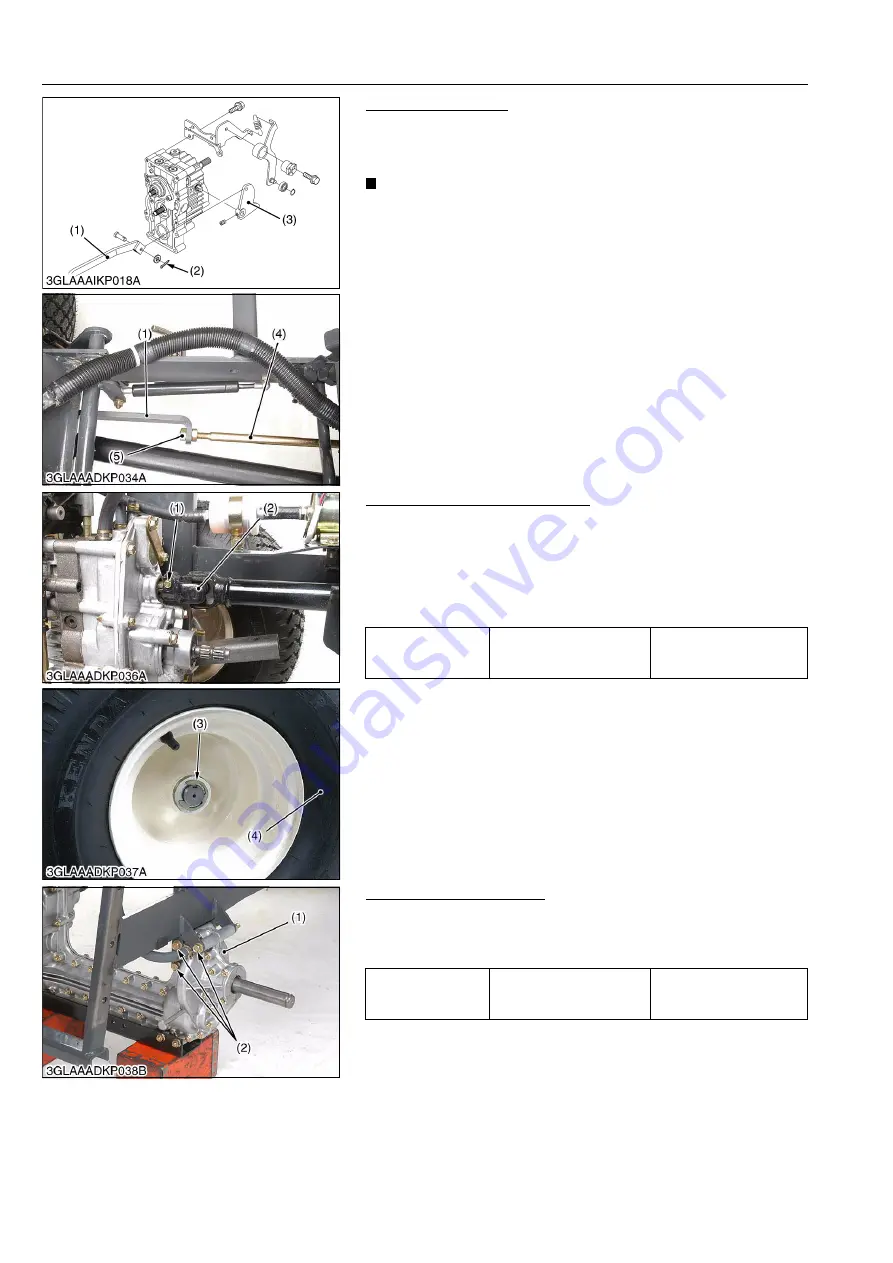
Speed Control Plate
1. Remove the split pin (2), and disconnect the speed change
plate (1) and speed control arm (3).
2. Separate the speed change plate (1) and speed change rod (4).
IMPORTANT
• After assembling the speed change plate (1) and speed
change rod (4), be sure to adjust the speed change pedal
restriction. (Refer to "[1] CHECKING AND ADJUSTING" on
page 2-S6.)
9Y1210595TXS0025US0
Universal Joint and Rear Wheel
1. Remove the universal joint mounting screw (1).
2. Disconnect the universal joint (2).
3. Block the front wheels with stopper, and lift up the frame.
4. Remove the retaining ring (3) and remove the rear wheel (4).
(When reassembling)
• Apply grease to the splines of the universal joint.
9Y1210595TXS0026US0
Separating Transmission
1. Remove the transaxle mounting screws (2).
2. Separate the transaxle (1) from the frame.
(When reassembling)
9Y1210595TXS0027US0
(1) Speed Change Plate
(2) Split Pin
(3) Speed Control Arm
(4) Speed Change Rod
(5) Lock Nut
Tightening torque
Universal joint mounting
screw
9.81 to 11.2 N·m
1.00 to 1.15 kgf·m
7.24 to 8.31 lbf·ft
(1) Universal Joint Mounting Screw
(2) Universal Joint
(3) Retaining Ring
(4) Rear Wheel
Tightening torque
Transaxle mounting screw
(2)
48 to 55 N·m
4.9 to 5.7 kgf·m
36 to 41 lbf·ft
(1) Transaxle
(2) Transaxle Mounting Screw
KiSC issued 11, 2013 A
Summary of Contents for GR1600EU
Page 1: ...GR1600EU WORKSHOP MANUAL KiSC issued 11 2013 A ...
Page 4: ...I INFORMATION KiSC issued 11 2013 A ...
Page 10: ...INFORMATION GR1600EU WSM I 5 9Y1210595INI0002US0 KiSC issued 11 2013 A ...
Page 11: ...INFORMATION GR1600EU WSM I 6 9Y1210595INI0003US0 KiSC issued 11 2013 A ...
Page 12: ...INFORMATION GR1600EU WSM I 7 9Y1210595INI0007US0 KiSC issued 11 2013 A ...
Page 16: ...INFORMATION GR1600EU WSM I 11 2 GR1600ID 9Y1210595INI0009US0 KiSC issued 11 2013 A ...
Page 17: ...G GENERAL KiSC issued 11 2013 A ...
Page 80: ...1 ENGINE KiSC issued 11 2013 A ...
Page 138: ...2 TRANSAXLE KiSC issued 11 2013 A ...
Page 194: ...3 BRAKES KiSC issued 11 2013 A ...
Page 195: ...CONTENTS 1 BRAKE MECHANISM 3 M1 MECHANISM KiSC issued 11 2013 A ...
Page 205: ...4 FRONT AXLE KiSC issued 11 2013 A ...
Page 213: ...5 STEERING KiSC issued 11 2013 A ...
Page 221: ...6 ELECTRICAL SYSTEM KiSC issued 11 2013 A ...
Page 223: ...ELECTRICAL SYSTEM GR1600EU WSM 6 M1 1 WIRING DIAGRAM 1 GR1600EU GR1600F KiSC issued 11 2013 A ...
Page 224: ...ELECTRICAL SYSTEM GR1600EU WSM 6 M2 2 GR1600ID KiSC issued 11 2013 A ...
Page 257: ...7 MOWER KiSC issued 11 2013 A ...


