ELECTRICAL SYSTEM
GR1600EU, WSM
6-M3
2. STARTING SYSTEM
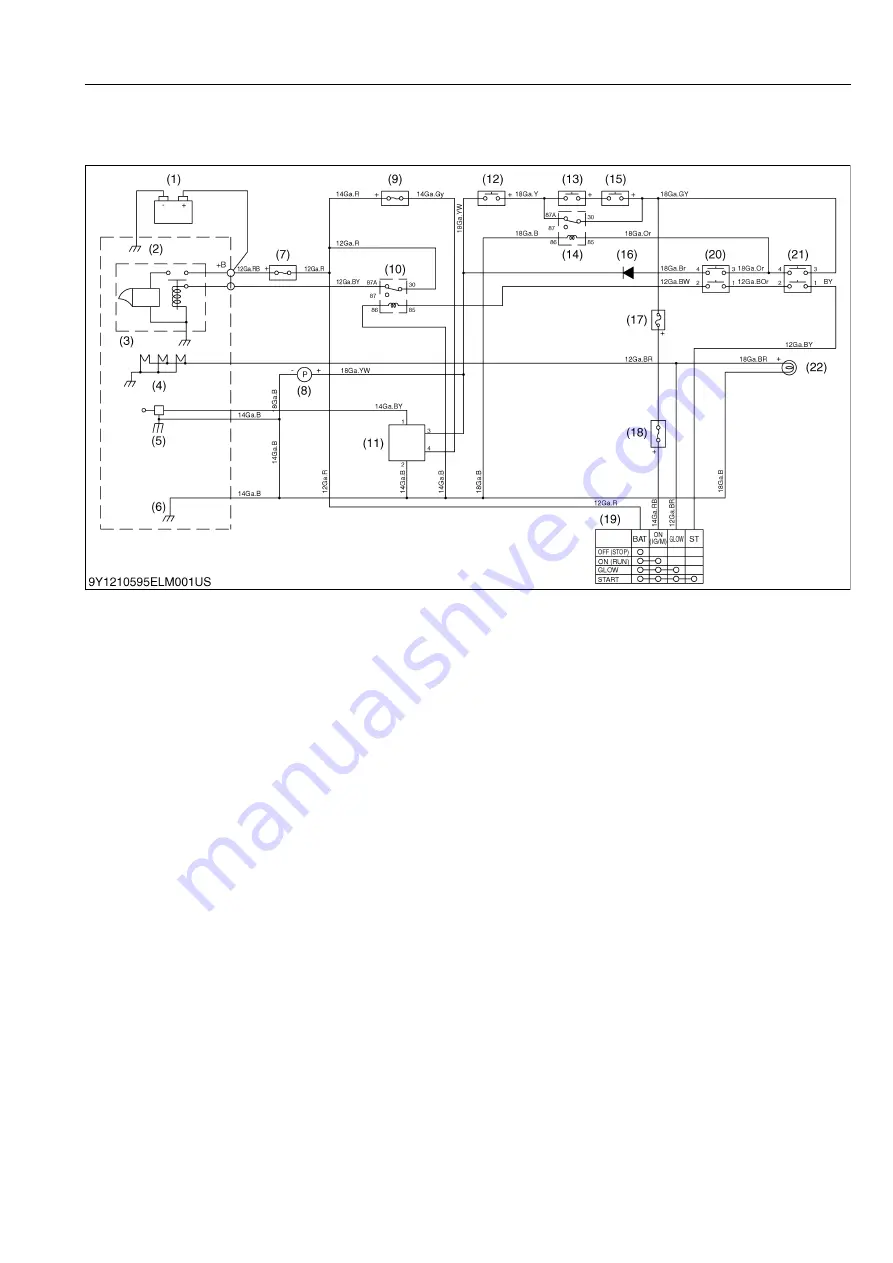
[1] GR1600EU, GR1600F
When the main switch (19) is turned to the
PREHEAT
position, the terminal
BAT
is connected to the terminals
GLOW
and
ON
. The glow plugs (4) become red-hot, and the glow plug (preheat indicator) lamp also lights on while
preheating.
When the main switch (19) is then turned to the
START
position with the brake switch (20) on and PTO switch
(21) on, the terminal
BAT
is connected to the terminals
START
and
ON
. Consequently, battery current flows to the
starter motor (3) and start the engine.
The main switch (19) automatically returns to the
ON
position, the terminal
BAT
is connected only to the terminal
ON
, thereby causing the starting circuit to be opened, stopping the starter motor (3).
When the main switch (19) turned from the
ON
position to the
OFF
position, the engine stop solenoid (5) moves
the fuel injection pump control rack to the
"No Fuel Injection"
position and stop the engine.
This machine equipped the operator presence control (OPC) system which automatically stops the engine when
operator stands from the seat while shifting the PTO lever.
With the PTO lever shifted to the
"ENGAGE"
position, the engine of this machine stops automatically when the
cover of the grass container opens, the grass container opens or dismounted.
9Y1210595ELM0001US0
(1) Battery
(2) GND
(3) Starter Motor
(4) Glow Plug
(5) Engine Stop Solenoid
(6) GND
(7) Slow Blow Fuse (40 A)
(8) Fuel Feed Pump
(9) Fuse (Engine Stop) (15 A)
(10) Starter Relay
(11) Engine Stop Time Relay
(12) Seat Switch
(13) Grass Container Open Switch
(14) Grass Container Open Relay
(15) Top Cover Open Switch
(16) Diode (3A)
(17) Fuse (OPC) (3 A)
(18) Fuse (IG/M) (10 A)
(19) Main Switch
(20) Brake Switch
(21) PTO Switch
(22) Glow Plug Lamp
KiSC issued 11, 2013 A
Summary of Contents for GR1600EU
Page 1: ...GR1600EU WORKSHOP MANUAL KiSC issued 11 2013 A ...
Page 4: ...I INFORMATION KiSC issued 11 2013 A ...
Page 10: ...INFORMATION GR1600EU WSM I 5 9Y1210595INI0002US0 KiSC issued 11 2013 A ...
Page 11: ...INFORMATION GR1600EU WSM I 6 9Y1210595INI0003US0 KiSC issued 11 2013 A ...
Page 12: ...INFORMATION GR1600EU WSM I 7 9Y1210595INI0007US0 KiSC issued 11 2013 A ...
Page 16: ...INFORMATION GR1600EU WSM I 11 2 GR1600ID 9Y1210595INI0009US0 KiSC issued 11 2013 A ...
Page 17: ...G GENERAL KiSC issued 11 2013 A ...
Page 80: ...1 ENGINE KiSC issued 11 2013 A ...
Page 138: ...2 TRANSAXLE KiSC issued 11 2013 A ...
Page 194: ...3 BRAKES KiSC issued 11 2013 A ...
Page 195: ...CONTENTS 1 BRAKE MECHANISM 3 M1 MECHANISM KiSC issued 11 2013 A ...
Page 205: ...4 FRONT AXLE KiSC issued 11 2013 A ...
Page 213: ...5 STEERING KiSC issued 11 2013 A ...
Page 221: ...6 ELECTRICAL SYSTEM KiSC issued 11 2013 A ...
Page 223: ...ELECTRICAL SYSTEM GR1600EU WSM 6 M1 1 WIRING DIAGRAM 1 GR1600EU GR1600F KiSC issued 11 2013 A ...
Page 224: ...ELECTRICAL SYSTEM GR1600EU WSM 6 M2 2 GR1600ID KiSC issued 11 2013 A ...
Page 257: ...7 MOWER KiSC issued 11 2013 A ...


