5
ENGLISH
B
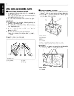
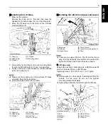
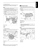
Installing the Lift Base
1. Draw out the cylinder.
Remove the snap pin (1) first and then draw the
headed pin (2) and cylinder (3) out of the lift base (4).
2. Move the lift base up to the level of the lift base
mounting frame (5).
3. Temporarily fix the lift base (4) to the mounting frame
(5) with the M10x25 bolts (7) (3 pcs. for each side).
4. Fix the cylinder (3) to the lift base (4) with the headed
pin (2) and snap pin (1).
A
Make sure the coupling (6) of the cylinder (3) faces
outwards. (See the figure below).
A
Insert the headed pin (2) from outside.
B
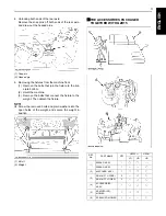
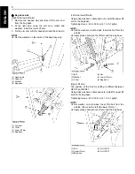
Installing the Lift Arms (Upper and Lower)
A
There are two upper lift arms. The lift arm that has a
stay is for the right side. Be careful not to confuse the
right and left ones and to keep the stay outward.
C
Lift base side
Using bolts, washers, collars and nuts, install the upper lift
arm and the lower lift arm to the lift base.
Tightening torque : 40 to 50 N-m (4.1 to 5.1 kgf-m)
A
Set the washer on the nut side. Insert the bolt from the
outside. For the lower lift arm, set the cylinder
mounting bracket downward
A
Apply grease between the lift arm and the lift base.
(1) Snap pin
(2) Headed pin
(3) Cylinder
(4) Lift base
(5) Mounting frame
(1) Snap pin
(2) Headed pin
(3) Cylinder
(4) Lift base
(5) Mounting frame
(6) Coupling
(7) M10 x 25 bolt
(1) Bag base
(2) Lift base
(3) Upper lift arm
(4) Lower lift arm
(5) Cylinder mounting bracket
(6) Stay
(1) Bolt
(2) Washer
(3) Collar
(4) Nut
(5) Upper lift arm
(6) Lower lift arm
(7) Lift base


