background image

M-2

J SERIES, WSM

GENERATOR

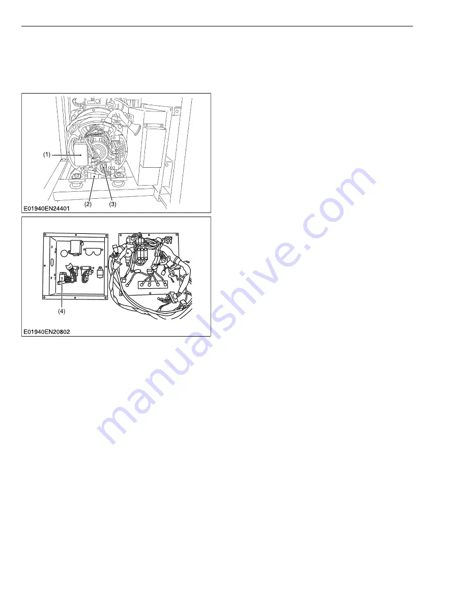
[2] AUTOMATIC  VOLTAGE  REGULATOR (A.V.R.)

NOTE

• It is hazardous to proceed to any high voltage test on the alternator without having previously

disconnected all connections to voltage regulator.
Damages occurring to A.V.R. in such conditions will not be considered in a warranty claim.

W1013858

(1) A.V.R.
(2) Capacitor
(3) Silicon Diode Stack
(4) Separate Excitation Unit

KiSC issued 10, 2016 A

Summary of Contents for J106-AUS

Page 1: ...WORKSHOP MANUAL DIESEL GENERATOR J SERIES KiSC issued 10 2016 A ...

Page 2: ...ntenance and special tools For each Engine and Generator section there are troubleshooting servicing specification lists checking and adjusting disassembling and assembling and servicing which cover procedures precautions factory specifications and allowable limits All information illustrations and specifications contained in this manual are based on the latest product information available at the...

Page 3: ...search function Search word to find all the revised locations Lastdigit of the Code No Issue month Main Revised Point and Corrective Measures Search word Reference Page 5 2016 10 AVR circuit changed M 10 to M 32 KiSC issued 10 2016 A ...

Page 4: ...ator itself to warn of the possibility of personal injury Read these instructions carefully It is essential that you read the instructions and safety regulations before you attempt to repair or use this unit DANGER Indicates an imminently hazardous situation which if not avoided will result in death or serious injury WARNING Indicates a potentially hazardous situation which if not avoided could re...

Page 5: ...therwise hot water will spout out from radiator Only remove radiator cap when cool enough to touch with bare hands Slowly loosen the cap to first stop to relieve pressure before removing completely Escaping fluid fuel under pressure can penetrate the skin causing serious injury Relieve pressure before disconnecting fuel lines Tighten all connections before applying pressure Wear a suitable hearing...

Page 6: ...s Keep electrolyte away from eyes hands and clothing If you spill electrolyte on yourself flush with water and get medical attention immediately DISPOSE OF FLUIDS PROPERLY Do not pour fluids into the ground down a drain or into a stream pond or lake Observe relevant environmental protection regulations when disposing of oil fuel coolant electrolyte and other harmful waste PREPARE FOR EMERGENCIES K...

Page 7: ...RUCTIONS The following safety decals are installed on the generator If a decal becomes damaged illegible or is not on the generator replace it The decal part number is listed in the parts list SAFETY DECALS KiSC issued 10 2016 A ...

Page 8: ...ber Compression ratio 23 1 22 1 Cooling system Pressurized radiator forced circulation with water pump Lubricating system Forced lubrication by trochoid pump Lubricating oil Higher than CD class API Starting system Electric type Stop solenoid Energized to stop Energized to run Battery 38B20R 55B24R 80D26R S Fuel tank capacity 37 L 9 8 U S gals 8 1 Imp gals 79 L 20 9 U S gals 17 4 Imp gals Cooling ...

Page 9: ...system Spherical combustion chamber Compression ratio 23 1 22 1 Cooling system Pressurized radiator forced circulation with water pump Lubricating system Forced lubrication by trochoid pump Lubricating oil Higher than CD class API Starting system Electric type Stop solenoid Energized to stop Energized to run Battery 55B24R 80D26R S Fuel tank capacity 37 L 9 8U S gals 8 1 Imp gals 79 L 20 9U S gals...

Page 10: ...m3 81 46 cu in Combustion system Spherical combustion chamber Compression ratio 23 1 22 1 Cooling system Pressurized radiator forced circulation with water pump Lubricating system Forced lubrication by trochoid pump Lubricating oil Higher than CD class API Starting system Electric type Stop solenoid Energized to stop Energized to run Battery 38B20R 55B24R 80D26R S Fuel tank capacity 37 L 9 8U S ga...

Page 11: ...system Pressurized radiator forced circulation with water pump Lubricating system Forced lubrication by trochoid pump Lubricating oil Higher than CD class API Starting system Electric type Stop solenoid Energized to stop Energized to run Battery 55B24R 80D26R S Fuel tank capacity 37 L 9 8U S gals 8 1 Imp gals 79 L 20 9U S gals 17 4 Imp gals Cooling system capacity 3 0 L 3 2U S qts 2 6 Imp qts 3 3 ...

Page 12: ...0 STD SA J310 STD AUS J313 STD J112 STD AUS J114 STD SA J315 STD AUS J318 STD J116 STD AUS J119 STD SA J320 STD AUS J324 STD Length mm in 923 36 4 995 39 2 1215 47 8 1300 51 1 Width mm in 593 23 3 593 23 3 611 24 1 611 24 1 Height mm in 860 33 8 860 33 8 922 36 3 922 36 3 KiSC issued 10 2016 A ...

Page 13: ...HANISM 1 GENERATOR M 1 1 STRUCTURE M 1 2 AUTOMATIC VOLTAGE REGULATOR A V R M 2 3 EMERGENCY RELAY CIRCUIT M 4 1 General M 4 2 Instructions M 5 3 Flow Chart M 7 4 EARTH M 9 5 WIRING DIAGRAM M 10 KiSC issued 10 2016 A ...

Page 14: ...R assembly 2 Rotor Assembly The coils are wound to magnetize the entire core 3 Brush Holder Assembly The excitation voltage from sub coil of the stator assembly is applied to the rotor coil through the A V R assembly rectifying circuit and the brush holder assembly 4 Automatic Voltage Regulator A V R Assembly The A V R assembly maintains the AC output voltage at a constant level 1 Rear Cover 2 A V...

Page 15: ...y high voltage test on the alternator without having previously disconnected all connections to voltage regulator Damages occurring to A V R in such conditions will not be considered in a warranty claim W1013858 1 A V R 2 Capacitor 3 Silicon Diode Stack 4 Separate Excitation Unit KiSC issued 10 2016 A ...

Page 16: ...4 Drive circuit The drive circuit 5 is basically composed of multiple transistors The drive signal being picked up by the photocoupler s light receiver is weak To intensify this signal the final stage transistor 4 that switches on and off the current to the rotor is activated For comparison let s imagine a gearbox that gives a large torque from a small force While the engine is stopped or in the l...

Page 17: ...at drive circuit Relay working current about 25 mA With key switch on About 10mA at drive circuit Relay working current about 25 mA Battery voltage rotor resistance A When the key switch 15 is turned on a small current below the decimal that is inversely proportional to the rotor resistance starts flowing continuously When the rotor voltage and rotor resistance are 12 V and 30 respectively for exa...

Page 18: ...e circuit 7 Drives the relay circuit 8 for a given delay time upon receipt of an output from the drive timer Consists of a power transistor and a diode to remove surge volts from the relay Relay circuit 8 Provides output to the stop solenoid 11 through a power relay A variator is incorporated to prevent surge voltage that would be otherwise generated when current to the stop solenoid 11 is cut off...

Page 19: ...delay timer 6 and force the engine to a stop The drive circuit 10 is also activated by grounding this terminal Drive circuit 10 This circuit is used to drive the built in relay 9 that turns on the non energized at the stop solenoid 11 The drive circuit 10 consists of relay drive transistor feedback diodes etc 3 Circuit behavior For a certain time after the key switch 1 has been set to the start po...

Page 20: ...M 7 GENERATOR J SERIES WSM 3 Flow Chart KiSC issued 10 2016 A ...

Page 21: ...M 8 J SERIES WSM GENERATOR W1012333 KiSC issued 10 2016 A ...

Page 22: ...tment to determine the approved generator grounding method to be used in his application or location Recommendations in the NEC NFPA and OSHA regulations must be followed to assure compliance and safe operation A grounding lug is provided on the KUBOTA generator frame for earth grounding depending on local state national or OSHA requirements One possible connection method for construction site use...

Page 23: ...M 10 J SERIES WSM GENERATOR 5 WIRING DIAGRAM KiSC issued 10 2016 A ...

Page 24: ...M 11 GENERATOR J SERIES WSM KiSC issued 10 2016 A ...

Page 25: ...M 12 J SERIES WSM GENERATOR KiSC issued 10 2016 A ...

Page 26: ...M 13 GENERATOR J SERIES WSM KiSC issued 10 2016 A ...

Page 27: ...M 14 J SERIES WSM GENERATOR KiSC issued 10 2016 A ...

Page 28: ...M 15 GENERATOR J SERIES WSM KiSC issued 10 2016 A ...

Page 29: ...M 16 J SERIES WSM GENERATOR KiSC issued 10 2016 A ...

Page 30: ...M 17 GENERATOR J SERIES WSM KiSC issued 10 2016 A ...

Page 31: ...M 18 J SERIES WSM GENERATOR KiSC issued 10 2016 A ...

Page 32: ...M 19 GENERATOR J SERIES WSM KiSC issued 10 2016 A ...

Page 33: ...M 20 J SERIES WSM GENERATOR KiSC issued 10 2016 A ...

Page 34: ...M 21 GENERATOR J SERIES WSM KiSC issued 10 2016 A ...

Page 35: ...M 22 J SERIES WSM GENERATOR KiSC issued 10 2016 A ...

Page 36: ...M 23 GENERATOR J SERIES WSM KiSC issued 10 2016 A ...

Page 37: ...M 24 J SERIES WSM GENERATOR KiSC issued 10 2016 A ...

Page 38: ...M 25 GENERATOR J SERIES WSM KiSC issued 10 2016 A ...

Page 39: ...M 26 J SERIES WSM GENERATOR KiSC issued 10 2016 A ...

Page 40: ...M 27 GENERATOR J SERIES WSM KiSC issued 10 2016 A ...

Page 41: ...M 28 J SERIES WSM GENERATOR KiSC issued 10 2016 A ...

Page 42: ...M 29 GENERATOR J SERIES WSM KiSC issued 10 2016 A ...

Page 43: ...M 30 J SERIES WSM GENERATOR KiSC issued 10 2016 A ...

Page 44: ...M 31 GENERATOR J SERIES WSM KiSC issued 10 2016 A ...

Page 45: ...M 32 J SERIES WSM GENERATOR KiSC issued 10 2016 A ...

Page 46: ... 1 DISASSEMBLING AND ASSEMBLING S 49 1 External Component S 49 2 Generator S 50 2 SERVICING S 52 1 Terminal Voltage for Each Part During Normal Periods No load Periods S 52 2 Stator Coil S 52 3 Rotor Coil S 53 4 Exciter Coil S 54 5 Control Panel S 54 6 Emergency Relay Activates S 55 3 ENGINE S 58 1 ENGINE BODY S 58 1 Checking and Adjusting S 58 2 Disassembling and Assembling S 61 3 Servicing S 76 ...

Page 47: ...IFICATION When contacting your local KUBOTA distributor always specify the model name and serial numbers of both engine and generator W11787580 1 Generator Serial Number 2 Generator Model Name 3 Engine Model Name and Serial Number KiSC issued 10 2016 A ...

Page 48: ...eassembling external snap rings or internal snap rings they must be positioned so that sharp edge faces against the direction from which a force is applied See the figure left Use only metric tools when servicing this machine Metric screws bolts and nuts are not interchangeable with nonmetric fasteners W11793520 Before checking any generator or engine electrical component be sure to check that all...

Page 49: ...J324 STD 5 7 L 6 0 U S qts 5 0 Imp qts Fuel J106 STD AUS J107 STD SA J108 STD AUS J110 STD SA J310 STD AUS J313 STD 37 L 9 8 U S gals 8 1 Imp gals Diesel fuel No 2 D No 1 D diesel fuel if temperature is below 10 C 14 F J112 STD AUS J114 STD SA J315 STD AUS J318 STD J116 STD AUS J119 STD SA J320 STD AUS J324 STD 79 L 20 9 U S gals 17 4 Imp gals Coolant J106 STD AUS J107 STD SA 2 3 L 2 4 U S qts 2 0...

Page 50: ...ernator Measuring equipment Voltmeter Ammeter Ambient temperature Air flow inlet outlet partially clogged or hot air is being recycled either from alternator or prime mover Alternator overloaded Fan belt slips Excessive vibration and humming noise coming from the alternator Stop the gen set and check the installation and others Three phase alternator is single phase loaded in excess of acceptable ...

Page 51: ...ive wear of brush or improper contact of it Defective slip ring Replace brush and clean the contact surface of it Disconnected exciter coil Repair or replace Defective A V R Replace Disconnected battery Connect battery NFB goes OFF Same as above Output voltage is normal 95 to 114 of rated voltage Abnormality of loading circuit Locate the cause Short circuit overloaded etc and remove it Improper co...

Page 52: ... normal Defective contact of circuit breaker Replace Discontinuity in one phase Repair or replace the stator Voltmeter does not indicate any voltage and also no output voltage is delivered Same as above Set the circuit breaker to ON 0 V output for all three phase Discontinuity in output coil Repair or replace the stator Simultaneous shorting of three phases Inspect the stator or wiring 0 V for one...

Page 53: ...n output coil Repair or replace the stator Abnormally high output voltages for all three phases 250 V or more phase voltage Defective contact of A V R connector Inspect and repair A V R failure Replace Measure the engine speed variation or frequency variation at no load and in loaded state Variation of engine speed is normal A V R failure Replace Defective contact of A V R connector Inspect and re...

Page 54: ...S 8 J SERIES WSM GENERAL D Engine Circuit Troubleshooting Z482 D722 KiSC issued 10 2016 A ...

Page 55: ...S 9 J SERIES WSM GENERAL KiSC issued 10 2016 A ...

Page 56: ...S 10 J SERIES WSM GENERAL KiSC issued 10 2016 A ...

Page 57: ...S 11 J SERIES WSM GENERAL KiSC issued 10 2016 A ...

Page 58: ...S 12 J SERIES WSM GENERAL KiSC issued 10 2016 A ...

Page 59: ...S 13 J SERIES WSM GENERAL E Engine Circuit Troubleshooting D1005 V1305 KiSC issued 10 2016 A ...

Page 60: ...S 14 J SERIES WSM GENERAL KiSC issued 10 2016 A ...

Page 61: ...functioning Wiring disconnected Replenish fuel Vent air Change fuel and repair or replace fuel system Clean Clean or change Use specified fuel or engine oil Use specified fuel Tighten retaining nut Adjust Replace Clean Repair or replace Repair or replace Replace head gasket tighten cylinder head screw glow plug and nozzle holder Correct or replace timing gear Replace Adjust Charge Repair or replac...

Page 62: ...on timing Engine s moving parts seem to be seizing Injection pump malfunctioning Deficient nozzle injection Compression leak Air cleaner dirty or clogged Adjust Repair or replace Repair or replace Repair or replace nozzle Check the compression pressure and repair Clean or replace S 105 S 106 S 58 S 40 Excessive Lubricant Oil Consumption Piston ring s gap facing the same direction Oil ring worn or ...

Page 63: ...e of oil Relief valve defective Use specified type of oil Replace S 3 Engine Overheated Engine oil insufficient Fan belt broken or elongated Coolant insufficient Radiator net and radiator fin clogged with dust Inside of radiator corroded Coolant flow route corroded Radiator cap defective Overload running Head gasket defective Incorrect injection timing Unsuitable fuel used Replenish Replace or adj...

Page 64: ...09 U O 0 61 0 32 0 25 V O 0 61 0 32 0 25 W O 0 61 0 32 0 25 Sub coil LG LG 2 6 2 0 2 2 1 8 2 6 2 1 Detecting coil R R 0 06 0 05 R B 0 07 0 05 0 04 R B 0 07 0 05 0 04 R B 0 07 0 05 0 04 Rotor coil 24 3 29 2 33 5 39 6 29 2 33 5 39 6 Air gap mm 0 8 Slip ring mm Outside diameter 64 Correction limit 62 5 Standard run out 0 1 Limit run out 0 15 Brush length mm Standard 15 Limit 7 5 Bearing 6306 DDUNCX R...

Page 65: ...0 40 0 28 V O 0 67 0 40 0 28 W O 0 67 0 40 0 28 Sub coil LG LG 2 6 2 0 2 2 1 8 2 6 2 3 Detecting coil R R 0 06 0 05 R B 0 07 0 05 0 04 R B 0 07 0 05 0 04 R B 0 07 0 05 0 04 Rotor coil 24 3 29 2 39 5 39 6 29 2 33 5 39 6 Air gap mm 0 8 Slip ring mm Outside diameter 64 Correction limit 62 5 Standard run out 0 1 Limit run out 0 15 Brush length mm Standard 15 Limit 7 5 Bearing 6306 DDUNCX Regulated vol...

Page 66: ... 2 3 0 10 0 06 3 4 0 06 0 04 U O 0 19 0 12 0 08 V O 0 19 0 12 0 08 W O 0 19 0 12 0 08 Sub coil LG LG 2 2 1 6 1 5 2 3 2 2 2 0 Detecting coil R R 0 05 0 04 R B 0 05 0 03 R B 0 05 0 03 R B 0 05 0 03 Rotor coil 24 3 29 2 33 5 39 6 29 2 33 5 39 6 Air gap mm 0 8 Slip ring mm Outside diameter 64 Correction limit 62 5 Standard run out 0 1 Limit run out 0 15 Brush length mm Standard 15 Limit 7 5 Bearing 63...

Page 67: ... 0 07 1 2 0 19 0 12 0 07 0 03 2 3 0 13 0 08 0 06 0 04 3 4 U O V O W O Sub coil LG LG 2 2 1 6 1 5 Detecting coil R R 0 05 0 04 R B R B R B Rotor coil 24 3 29 2 33 5 39 6 Air gap mm 0 8 Slip ring mm Outside diameter 64 Correction limit 62 5 Standard run out 0 1 Limit run out 0 15 Brush length mm Standard 15 Limit 7 5 Bearing 6306 DDUNCX Regulated voltage value 7 8 Circuit breaker capacity A 51 30 79...

Page 68: ... mm 0 00571 to 0 00728 in Valve Seat Width 2 12 mm 0 0835 in Valve Seat Angle 0 79 rad 45 Valve Face Angle 0 79 rad 45 Valve Recessing 0 10 to 0 10 mm 0 0039 to 0 0039 in 0 30 mm 0 0118 in Valve Stem to Valve Guide Valve Stem Valve Guide Clearance O D I D 0 030 to 0 057 mm 0 00118 to 0 00224 in 5 968 to 5 980 mm 0 23496 to 0 23543 in 6 010 to 6 025 mm 0 23661 to 0 23720 in 0 10 mm 0 0039 in Valve ...

Page 69: ...Push Rod Alignment 0 25 mm 0 0098 in Tappet to Tappet Guide Bore Tappet Tappet Guide Bore Clearance O D I D 0 016 to 0 052 mm 0 00063 to 0 00205 in 17 966 to 17 984 mm 0 70732 to 0 70803 in 18 000 to 18 018 mm 0 70866 to 0 70937 in 0 10 mm 0 0039 in Camshaft Side Clearance 0 15 to 0 31 mm 0 0059 to 0 0122 in 0 5 mm 0 0197 in Camshaft Alignment 0 01 mm 0 0004 in Cam Height Intake Exhaust 26 88 mm 1...

Page 70: ... D I D 0 020 to 0 084 mm 0 00079 to 0 00331 in 19 967 to 19 980 mm 0 78610 to 0 78661 in 20 000 to 20 051 mm 0 78740 to 0 78941 in 0 10 mm 0 0039 in Piston Pin Bore I D 20 000 to 20 013 mm 0 78740 to 0 78791 in 20 05 mm 0 7894 in Piston Ring Clearance Second Ring Oil Ring 0 090 to 0 120 mm 0 00354 to 0 00472 in 0 04 to 0 08 mm 0 0016 to 0 0031 in 0 15 mm 0 0059 in 0 15 mm 0 0059 in Ring Gap Top Ri...

Page 71: ... 0 00110 to 0 00232 in 39 934 to 39 950 mm 1 57221 to 1 57284 in 39 978 to 39 993 mm 1 57394 to 1 57453 in 0 20 mm 0 0079 in Crankpin to Crankpin Bearing Crankpin Crankpin Bearing Oil Clearance O D I D 0 020 to 0 051 mm 0 00079 to 0 00201 in 33 959 to 33 975 mm 1 33697 to 1 33760 in 33 995 to 34 010 mm 1 33839 to 1 33898 in 0 15 mm 0 0059 in Crankshaft Side Clearance 0 15 to 0 31 mm 0 0059 to 0 01...

Page 72: ...0 9 0 6 kgf cm2 13 9 psi Fan Belt Tension 7 0 to 9 0 mm 98 N 0 28 to 0 35 in 98 N 10kgf 22 lbs Injection Pump Injection Timing Z482 0 36 to 0 40 rad 20 5 to 22 5 before T D C D722 0 35 to 0 39 rad 20 to 22 before T D C Pump Element Fuel Tightness 14 7 MPa 150 kgf cm2 2130 psi Delivery Valve Fuel Tightness 5 seconds 14 7 13 7 MPa 150 140 kgf cm2 2130 1990 psi Fuel Injection Nozzle Injection Pressur...

Page 73: ...Factory Specification Allowable Limit Commutator O D 28 0 mm 1 10 in 27 0 mm 1 06 in Mica Undercut 0 50 to 0 80 mm 0 020 to 0 031 in 0 20 mm 0 0079 in Brush Lenght 16 0 mm 0 630 in 10 5 mm 0 413 in No load voltage AC 14 V or more at 86 7 s 1 5200 rpm Glow Plug Resistance Approx 0 9 KiSC issued 10 2016 A ...

Page 74: ...0 00728 in Valve Seat Width 2 12 mm 0 0835 in Valve Seat Angle Intake Angle Exhaust 1 05 rad 60 0 79 rad 45 Valve Face Angle Intake Angle Exhaust 1 05 rad 60 0 79 rad 45 Valve Recessing 0 05 to 0 15 mm 0 0020 to 0 0059 in 0 40 mm 0 0157 in Valve Stem to Valve Guide Valve Stem Valve Guide Clearance O D I D 0 035 to 0 065 mm 0 00138 to 0 00256 in 6 960 to 6 975 mm 0 27402 to 0 27461 in 7 010 to 7 02...

Page 75: ...ush Rod Alignment 0 25 mm 0 0098 in Tappet to Tappet Guide Bore Tappet Tappet Guide Bore Clearance O D I D 0 020 to 0 062 mm 0 00079 to 0 00244 in 19 959 to 19 980 mm 0 78579 to 0 78661 in 20 000 to 20 021 mm 0 78740 to 0 78823 in 0 07 mm 0 0028 in Camshaft Side Clearance 0 07 to 0 22 mm 0 0028 to 0 0087 in 0 30 mm 0 0118 in Camshaft Alignment 0 01 mm 0 0004 in Cam Height Intake Exhaust 28 80 mm 1...

Page 76: ...D 0 020 to 0 054 mm 0 00079 to 0 00213 in 25 967 to 25 980 mm 1 02232 to 1 02283 in 26 000 to 26 021 mm 1 02362 to 1 02445 in 0 10 mm 0 0039 in Piston Pin Bore I D 22 000 to 22 013 mm 0 86614 to 0 86665 in 22 05 mm 0 8681 in Piston Ring Clearance Second Ring Oil Ring 0 085 to 0 112 mm 0 00335 to 0 00441 in 0 020 to 0 055 mm 0 00079 to 0 00217 in 0 20 mm 0 0079 in 0 15 mm 0 0059 in Ring Gap Top Rin...

Page 77: ...59 to 39 975 mm 1 57319 to 1 57382 in 40 004 to 40 050 mm 1 57496 to 1 57677 in 0 20 mm 0 0079 in Crankshaft Journal to Crankshaft Bearing 3 Flywheel Side Crankshaft Journal Crankshaft Bearing 3 Oil Clearance O D I D 0 034 to 0 098 mm 0 00134 to 0 00386 in 51 921 to 51 940 mm 2 04413 to 2 04488 in 51 974 to 52 019 mm 2 04622 to 2 04799 in 0 20 mm 0 0079 in Crankshaft Side Clearance 0 15 to 0 31 mm...

Page 78: ...e is 12 7 MPa 130 kgf cm2 1850 psi the valve seat must be fuel tightness Item Factory Specification Allowable Limit Thermostat Valve Opening Temperature At Beginning Valve Opening Temperature Opened Completely 80 5 to 83 5 C 176 9 to 182 3 F 95 C 203 F Radiator Water Leakage Test Pressure No leaks at Specified pressure 137 kPa 1 4 kgf cm2 20 psi Radiator Cap Pressure Falling Time 10 seconds or mor...

Page 79: ...acteristics 13 5 V 30 A at 83 3 s 1 5000 rpm rpm Regulating Voltage 14 2 to 14 8 V No Load Characteristics 19 s 1 1150 rpm or less at 13 5 V Rotor Coil 2 9 Stator Coil 0 12 Slip Ring O D 14 4 mm 0 567 in 12 8 mm 0 504 in Brush Lenght 10 0 mm 0 394 in 8 5 mm 0 354 in Glow Plug Resistance Approx 0 9 KiSC issued 10 2016 A ...

Page 80: ... 0 to 2 8 18 1 to 25 3 14 5 to 20 3 14 5 to 20 3 14 5 to 20 3 Engine Cylinder head cover cap nut Injection pipe retaining nuts Nozzle holder assembly Over flow pipe assembly retaining nut Glow plug Roker arm bracket nuts Cylinder head screw Fan drive pulley retaining screw Idle gear shaft mounting screw Connecting rod screw Flywheel screw Bearing case cover mounting screw Main Bearing case screw 2...

Page 81: ...ew 1 Oil switch Starter B terminal nut Pulley nut 6 9 to 8 8 24 5 to 34 3 49 0 to 68 6 19 6 to 24 5 7 8 to 14 7 21 6 to 26 5 63 7 to 68 6 235 to 245 9 8 to 11 3 41 2 to 46 1 53 9 to 58 8 9 8 to 11 3 49 0 to 53 9 29 4 to 34 3 14 7 to 19 6 8 8 to 11 8 58 3 to 78 9 0 7 to 0 9 2 5 to 3 5 5 0 to 7 0 2 0 to 2 5 0 8 to 1 5 2 2 to 2 7 6 5 to 7 0 24 0 to 25 0 1 00 to 1 15 4 2 to 4 7 5 5 to 6 0 1 00 to 1 15...

Page 82: ... hours Every 300 hours Every 400 hours Every 500 hours Every 800 hours Every 1000 hours Every 1 year Every 2 years Reference page 1 Engine oil Checking S 38 Changing S 38 2 Radiator coolant L L C Checking S 38 Changing 3 Air cleaner element Cleaning S 40 Changing S 40 4 Fan belt Checking S 40 Changing 5 Fuel line Fuel line and clamps Checking S 39 Changing S 39 42 6 Battery Checking S 40 Changing ...

Page 83: ...e axial dislocation exceeds the allowable limit replace the bearing 1 Measure the I D of the bearing housing 2 If the wear exceeds the allowable limit replace the end bracket W12101460 C Check Points of Every 1 year Checking Damage in Electric Wiring and Loose Connections Refer to SERVICING section W1362595 Brush length Stretch out of the Holder Standard length 15 0 mm 0 59 in Allowable limit 7 5 ...

Page 84: ...l the radiator before opening the cap 1 Remove the radiator cap and check to see that the coolant level is just below the port 2 If low add coolant to the radiator 3 Check the reserve tank 1 and keep the coolant level between the FULL and LOW marks 4 If low add coolant to the reserve tank 1 W12114660 B Check Points of Initial 50 Hours Changing Engine Oil CAUTION Be sure to stop the engine before c...

Page 85: ...nge prescribed below Remember to check the fuel line periodically The fuel line is subject to wear and aging fuel may leak out onto the running engine causing a fire 1 Check to see that all fuel lines 2 and hose clamps 1 are tight and not damaged 2 If lines and clamps are found worn or damaged replace or repair them at once 3 The fuel line 2 is made of rubber and ages regardless of period of servi...

Page 86: ...lyte level 2 If the level is below than lower level line 2 add the distilled water to pour level of each cell 3 If the battery can not be charged even though the electrolyte level is correct replace the battery W12147130 Fan Belt Tension 1 Measure the deflection A depressing the belt halfway between the fan drive pulley and alternator at specified force 98 N 10 kgf 22 lbs 2 If the measurement is n...

Page 87: ...d or cracked W12221550 Changing Engine Oil Filter Cartridge 1 See page S 39 W12225020 F Check Points of Every 400 Hours Changing Fuel Filter Element 1 Close the fuel cock 1 2 Remove the fuel filter element 2 3 Install the new fuel filter element screwing it in by hand NOTE Check for fuel leak after replaced it W12228140 G Check Points of Every 500 Hours Changing Fan belt 1 See page S 40 W1363103 C...

Page 88: ... Radiator Hose and Clamp CAUTION Before changing the radiator hoses and clamps be sure to stop the engine Never open the pressure cap while the engine is running under heavy loads or immediately after the engine has stopped Otherwise hot water may spray out scalding the operator So make it a habit to wait for about 10 minutes before opening the cap 1 To drain the coolant open the drain cock and re...

Page 89: ...compression and diagnostics of need for major overhaul W12271130 Oil Pressure Tester Code No 07916 32032 Application Use to measure lubricating oil pressure W12274130 Press Gauge Code No 07909 30241 Application Use to check the oil clearance between crankshaft and bearing etc Measureing Green 0 025 to 0 076 mm range 0 001 to 0 003 in Red 0 051 to 0 152 mm 0 002 to 0 006 in Blue 0 102 to 0 229 mm 0...

Page 90: ...nd I D 30 to 75 mm 1 18 to 2 95 in dia Connecting rod length 65 to 330 mm 2 56 to 12 99 in W12288380 Red Check Crack Check Liquid Code No 07909 31371 Application Use to check cracks on cylinder head cylinder block etc W12296340 Flywheel Puller Code No 07916 32011 Application Use exclusively for removing the flywheel with ease W12299460 Auxiliary Socket for Fixing Crankshaft Sleeve Z482 D722 Code N...

Page 91: ...le More than 29 4 MPa 300 kgf cm2 4267 psi B Copper gasket C Flange Material Steel D Hex nut 27 mm 1 06 in across the plat E Injection pipe F PF 1 2 G 5 mm 0 20 in H 17 mm dia 0 67 in dia I 8 mm dia 0 31 in dia J 1 0 mm 0 039 in K 17 mm dia 0 67 in dia L 6 10 to 6 20 mm dia 0 2402 to 0 2441 in dia M 8 mm 0 31 in N 4 mm 0 16 in O 11 97 to 11 99 mm dia 0 4713 to 0 4721 in dia P PF 1 2 Q 23 mm 0 91 i...

Page 92: ... 0 71 in dia K 10 6 to 10 7 mm dia 0 417 to 0 421 in dia L 7mm 0 276 in C1 Chamfer 1 0 mm 0 039 in C2 Chamfer 2 0 mm 0 079 in C0 3 Chamfer 0 3 mm 0 012 in A 20 mm dia 0 79 in dia B 11 7 to 11 9 mm dia 0 460 to 0 468 in dia C 6 5 to 6 6 mm dia 0 256 to 0 259 in dia D 225 mm 8 86 in E 70 mm 2 76 in F 45 mm 1 77 in G 25 mm 0 98 in H 5 mm 0 197 in I 6 7 to 7 0 mm dia 0 263 to 0 275 in dia J 20 mm dia ...

Page 93: ... 8642 in dia E 25 mm dia 0 98 in dia F 19 90 to 19 95 mm dia 0 7835 to 0 7854 in dia A 196 mm 7 72 in B 26 mm 1 02 in C 150 mm 5 91 in D 25 8 to 25 9 mm dia 1 0157 to 1 0197 in dia E 28 8 to 28 9 mm dia 1 0157 to 1 0197 in dia F 20 mm dia 0 7874 in dia A 145 mm 5 71 in B 25 mm 0 98 in C 20 mm 0 79 in D 21 90 to 21 95 mm dia 0 8622 to 0 8642 in dia E 25 mm dia 0 98 in dia F 19 91 to 19 95 mm dia 0 ...

Page 94: ... dia H 39 90 to 39 95 mm dia 1 5709 to 1 5728 in dia A 135 mm 5 31 in B 72 mm 2 83 in C 1 57 rad 40 D 10 mm 0 39 in E 20 mm 0 79 in F 20 mm dia 0 79 in dia G 56 80 to 56 90 mm dia 2 2362 to 2 2402 in dia H 51 80 to 51 90 mm dia 2 0393 to 2 0433 in dia A 130 mm 5 12 in B 72 mm 2 83 in C 1 57 rad 40 D 9 mm 0 35 in E 24 mm 0 95 in F 20 mm dia 0 79 in dia G 68 mm dia 2 68 in dia 2 2362 to 2 2402 in di...

Page 95: ...ternator AC dynamo the fuse box and the earth 4 Drain the coolant and engine oil and remove each fuel hose 5 Remove the muffler pipe 7 fuel tank cap 6 rubber seal 5 and the bonnet 4 6 Remove the fuel tank 1 7 Remove the generator s rear cover 3 and disconnect the lead wire from the stator coil 8 Remove the control panel 8 9 Remove the radiator hose both side and the panel with the radiator 9 W1244...

Page 96: ...ition the bearing correctly Misalignment may make it difficult to install the bearing or what s worse damage it IMPORTANT Be careful not to confuse the direction of the snap ring of the bearing W12449310 Stator Assembly and Stator Housing 1 Hoist up the stator assembly 1 2 Remove the stator assembly 1 take care not to damage the winding and the rotor 3 Remove the stator housing 2 When reassembling...

Page 97: ...age of rotor and stator caused by loose fittings Handle carefully to avoid damaging the winding W1105701 Replacing Ball Bearing When removing 1 Hook the puller until it clicks onto the outer bearing ring and then pull off the bearing When installing Keep new bearing sealed until use Clean dirt from the bearing housing When tapping in the bearing press it by tapping on the inner race gently with sp...

Page 98: ...he resistance is not as specified replace the stator coil or contact service station Measurement is not possible with a regular tester W1107122 Detecting Coil 1 Measure the coil resistance between each auxiliary winding 2 If the factory specification is not indicated replace the stator coil or contact service station W1109041 Grounding of Stator Coil 1 Measure the insulation resistance between eac...

Page 99: ...ds carefully It is a good idea to tag them during disassembly 3 A diode in a good condition enables the current to flow in only one direction from anode to cathode 4 If the diode is faulty contact service station or replace with revolving rectifier assembly W1111526 Checking Ball Bearing 1 Measure radial dislocation of the outer ring 2 If the axial dislocation exceeds the allowable limit replace t...

Page 100: ...us replace the exciter coil assembly or contact service station W1113425 5 Control Panel Circuit Breaker NFB 1 Test for continuity between the each upper and lower breaker terminals with an ohmmeter 2 Confirm that there is continuity when the breaker switch in ON 3 If there is no continuity it indicates that the contacts are faulty Replace the breaker NOTE When there is a short circuit in the wiri...

Page 101: ...engine has stopped check the cause and repair it Emergency Relay Circuit 1 When the engine is running at rated rpm s connect the lead wires to the terminal of the oil switch 1 or the water temperature switch 2 2 Also ground the other end of the lead wires to an unpainted portion of the engine frame In normal operation The stop solenoid release and the engine stops automatically As the stop solenoi...

Page 102: ...switch apply sealing agent to the threads and then screw it in firmly Make a test run after installation to check for any water leaks W1116632 Stop Solenoid Z482 D722 1 Connect the battery to the lead wire of the stop solenoid and the to the body to check stop solenoid functioning 2 It is normal if the plunger is attracted forcibly and defective if not 3 Replace the solenoid if it is defective IMP...

Page 103: ...ey switch turn to ON position then the solenoid should operate strongly with an audible click if not 3 Remove the solenoid and check the continuity of pull coil and hold coil as well as checking plunger moving 4 Replace the solenoid if it is defective W1117759 ST MB 3L 1 Lead Wire a Starter KiSC issued 10 2016 A ...

Page 104: ... ring top clearance valve and cylinder head 6 If the measurement is below the allowable limit apply a small amount of oil to the cylinder wall through the nozzle hole and measure the compression pressure again 7 If the compression pressure is still less than the allowable limit check the top clearance valve and cylinder head 8 If the compression pressure increases after applying oil check the cyli...

Page 105: ...he crank shaft until the piston exceeds its top dead center 5 Remove the cylinder head and measure squeezed fuse wires for thickness 6 If the measurement is not within the specified value check the oil clearance of the crankpin journal and the piston pin NOTE After checking the top clearance be sure to assemble the cylinder head with a new cylinder head gasket W10107670 Top clearance Factory spec ...

Page 106: ...t the compression top dead center or the overlap position Now referring to the table below readjust the valve clearance The piston is at the compression top dead center when both the IN and EX valves do not move it is at the overlap position when both the valves move Finally turn the flywheel 6 28 rad 360 and align the TC marking line and the center of timing window Adjust all the other valve clea...

Page 107: ...4 in 1 Drive screw driver lightly into the heat seal hole 2 Turn screw driver three or four times each way 3 While turning the screw driver slowly pull the heat seal out together with the injection nozzle gasket If the heat seal drops repeat the above procedure Heat seal and copper gaskets must be changed when the injection nozzle is removed for cleaning or for service W10154410 Tightening torque ...

Page 108: ...head screw gradually screw in the order of 1 to 10 14 or 18 after applying engine oil Retighten the cylinder head screw after running the engine for 30 minutes NOTE Mark the cylinder number to the tappets to prevent interchanging When reusing the head bolt apply engine oil to its thread when use a new head bolt rust preventive oil applied use it without applying engine oil to it and seat surface b...

Page 109: ... When reassembling Hook the spring 4 to the lever 5 first and install the speed control plate 2 Be sure to place the copper washers underneath two screws 1 as shown in the figure Position the slot 9 on the fork lever just under the slot 8 on the crankcase Insert the injection pump 3 so that the control rod 7 should be pushed by the spring 6 at its end and the pin 10 on the rod engages with the slo...

Page 110: ... 1 Remove the screw 1 of inside the gear case and outside screws 2 Disconnect the start spring 2 in the speed control plate mounting hole 3 Remove the gear case 3 When reassembling Apply a liquid gasket Three Bond 1215 or equivalent to both sides of the gear case gasket 4 Be sure to set three O rings 5 inside the gear case W10174840 Tightening torque Fan drive pulley retaining screw 118 to 127 N m...

Page 111: ...ly to the camshaft before installation W10177050 Fuel Camshaft and Fork Lever Holder 1 Remove the fuel camshaft stopper plate 2 Remove the fork lever holder mounting screws 3 Remove the fuel camshaft with injection pump gear 1 and the fork lever holder at the same time W10178820 Oil Pump and Crankshaft Gear 1 Remove the oil pump gear 6 2 Remove the oil pump 5 3 Remove the collar 4 O ring 3 and oil...

Page 112: ... the fan drive pulley to the crankshaft aligning the aligning marks 3 on them W10181950 Water Pump 1 Remove the water pump flange When reassembling Before installing the water pump flange gasket apply liquid gasket Three Bond 1215 or equivalent to the both side W10243100 Tightening torque Fan drive pulley retaining screw 235 to 245 N m 24 0 to 25 0 kgf m 174 to 181 ft lbs 1 Crankshaft Screw 2 Fan ...

Page 113: ...s Refer to the figure W10243800 Speed Control Plate 1 Remove the speed control plate and governor lever 1 from the governor spring 1 2 and governor spring 2 3 When reassembling Securely catch the governor spring 1 and governor spring 2 on the governor lever as shown in the figure Apply a liquid gasket Three Bond 1215 or equivalent to both sides of the speed control plate gasket W10250510 A 45 mm 1...

Page 114: ...s 0 05 mm 0 0020 in delays or advances the injection timing by approx 0 0087 rad 0 5 In disassembling and replacing be sure to use the same number of new shims with the same thickness W10252510 Fuel Camshaft 1 Remove the fuel camshaft stopper 4 2 Draw out the fuel camshaft 5 and injection pump gear 3 3 Remove the fuel feed pump cam 1 and washer 2 from the injection pump gear 3 When reassembling Ap...

Page 115: ...ft Check the governor shaft for smooth rotation IMPORTANT When replacing the ball bearing of governor shaft securely fit the ball bearing 3 to the crankcase apply an adhesive Three Bond 1324B or equivalent to the set screw 4 and fasten screw until its tapered part contacts the circumferential end of the ball bearing W10257780 1 External Snap Ring 2 Governor Shaft 3 Ball Bearing 4 Set Screw KiSC is...

Page 116: ...then remove the idle gear 4 2 Remove the camshaft stopper mounting screw and pull out the camshaft 6 When reassembling Apply engine oil to the idle gear shaft mounting screws And tighten them When installing the idle gear be sure to align the alignment marks a b and c on the gears Securely fit the external snap ring and stopper W10263250 1 Fork Lever Shaft Cover 2 Spacer 3 Bearing 4 Fork Lever Sha...

Page 117: ... the center of the flange as well as on the inner wall of each bolt hole Cut the nozzle of the fluid sealant container at its second notch Apply fluid sealant about 5 mm 0 20 in thick Within 20 minutes after the application of fluid sealant reassemble the components Wait then for about 30 minutes and pour oil in the crankcase W10265670 Connecting Rod Cap 1 Remove the connecting rod caps When reass...

Page 118: ... the mark on the connecting rod to the injection pump IMPORTANT Do not change the combination of cylinder and piston Make sure of the position of each piston by marking For example mark 1 on the No 1 piston Place the piston rings with their gaps at 0 79 rad 45 from the piston pin s direction as shown in the figure Carefully insert the pistons using a piston ring compressor Otherwise their chrome p...

Page 119: ...f the oil ring gap 11 Apply engine oil to the piston pin When installing the piston pin immerse the piston in 80 C 176 F oil for 10 to 15 minutes and insert the piston pin to the piston When installing the connecting rod to the piston align the mark 8 on the connecting rod to the fan shaped concave 9 IMPORTANT Mark the same number on the connecting rod and the piston so as not to change the combin...

Page 120: ...ase cover 5 to remove it IMPORTANT The length of inside screws and outside screws are different Do not take a mistake using inside screws and outside screws When reassembling Fit the bearing case gasket 1 and the bearing case cover gasket 2 with correct directions Install the bearing case cover to position the casting mark UP on it upward Apply engine oil to the oil seal lip and take care that it ...

Page 121: ...lean engine oil on the bearings Install the main bearing case assemblies in the original positions Since diameters of main bearing case vary install them in order of makings A B from the gear case side Match the alignment numbers 1 on the main bearing case When installing the main bearing case 1 and 2 face the mark FLYWHEEL to the flywheel Apply engine oil to the main bearing case screw 1 Install ...

Page 122: ...eck the valve recessing after correcting W10301620 Cylinder Head Flaw 1 Prepare an air spray red check Code No 07909 31371 2 Clean the surface of the cylinder head with detergent 2 3 Spray the cylinder head surface with the red permeative liquid 1 Leave it five to ten minutes after spraying 4 Wash away the red permeative liquid on the cylinder head surface with the detergent 2 5 Spray the cylinder...

Page 123: ...valve guide Lap the valve onto its seat with a valve flapper or screwdriver 3 After lapping the valve wash the compound away and apply oil then repeat valve lapping with oil 4 Apply prussian to the contact surface to check the seated rate If it is less than 70 repeat valve lapping again IMPORTANT When valve lapping is performed be sure to check the valve recessing and adjust the valve clearance af...

Page 124: ...ecisely the I D of the valve guide to the specified dimension IMPORTANT Do not hit the valve guide with a hammer during replacement W10314690 Clearance between valve stem and valve guide Factory spec 0 030 to 0 057 mm 0 00118 to 0 00224 in Allowable limit 0 10 mm 0 0039 in Valve stem O D Factory spec 5 968 to 5 980 mm 0 23496 to 0 23543 in Valve guide I D Factory spec 6 010 to 6 025 mm 0 23661 to ...

Page 125: ...eat cutter to exhaust valve seat so that the width is close to specified valve seat width 2 12 mm 0 0835 in 2 After resurfacing the seat inspect for even valve seating apply a thin film of compound between the valve face and valve seat and fit them with valve lapping tool 3 Check the valve seating with prussian blue The valve seating surface should show good contact all the way around W10319540 In...

Page 126: ...mpress it to the same length it is actually compressed the engine 2 Read the compression load on the gauge 3 If the measurement is less than the allowable limit replace it Z482 D722 D1005 V1305 W11177330 Free length A Factory spec 31 3 to 31 8 mm 1 23 to 1 25 in Allowable limit 28 4 mm 1 12 in Tilt B Allowable limit 1 2 mm 0 047 in Free length A Factory spec 37 0 to 37 5 mm 1 46 to 1 48 in Allowab...

Page 127: ...ent 3 If the measurement exceed the allowable limit replace the push rod W11220210 Oil clearance between rocker arm and rocker arm shaft Factory spec 0 016 to 0 045 mm 0 00063 to 0 00177 in Allowable limit 0 15 mm 0 0059 in Rocker arm shaft O D Factory spec 10 473 to 10 484 mm 0 41232 to 0 41276 in Rocker arm I D Factory spec 10 500 to 10 518 mm 0 41339 to 0 41410 in Oil clearance between rocker a...

Page 128: ...etween tappet and tappet guide bore Factory spec 0 016 to 0 052 mm 0 00063 to 0 00205 in Allowable limit 0 10 mm 0 0039 in Tappet O D Factory spec 17 966 to 17 984 mm 0 70732 to 0 70803 in Tappet guide bore I D Factory spec 18 000 to 18 018 mm 0 70866 to 0 70937 in Oil clearance between tappet and tappet guide bore Factory spec 0 020 to 0 062 mm 0 00079 to 0 00244 in Allowable limit 0 07 mm 0 0028...

Page 129: ... 0059 in Backlash between idle gear and injection pump gear Factory spec 0 041 to 0 124 mm 0 00165 to 0 00484 in Allowable limit 0 15 mm 0 0059 in Backlash between oil pump drive gear and crank gear Factory spec 0 041 to 0 123 mm 0 00161 to 0 00484 in Allowable limit 0 15 mm 0 0059 in Backlash between idle gear and crank gear Factory spec 0 032 to 0 115 mm 0 00120 to 0 00453 in Allowable limit 0 1...

Page 130: ...ent 1 Support the camshaft with V blocks on the surface plate at both end journals 2 Set a dial indicator with its tip on the intermediate journal 3 Measure the camshaft alignment 4 If the measurement exceeds the allowable limit replace the camshaft W11312720 Idle gear side clearance Factory spec 0 20 to 0 46 mm 0 0079 to 0 0180 in Allowable limit 0 60 mm 0 0236 in Idle gear side clearance Factory...

Page 131: ...able limit 26 83 mm 1 0563 in Cam height of intake Factory spec 28 80 mm 1 1339 in Allowable limit 28 75 mm 1 1319 in Cam height of exhaust Factory spec 29 00 mm 1 1417 in Allowable limit 28 95 mm 1 1398 in Oil clearance of camshaft journal Factory spec 0 050 to 0 091 mm 0 00197 to 0 00358 in Allowable limit 0 15 mm 0 0059 in Camshaft journal O D Factory spec 32 934 to 32 950 mm 1 2966 to 1 29724 ...

Page 132: ... apply engine oil to them 2 Press in a new brushing using an idle gear bushing replacing tool until it is flush with the end of the idle gear W11373220 Oil clearance between idle gear shaft and idle gear bushing Factory spec 0 020 to 0 084 mm 0 00079 to 0 00331 in Allowable limit 0 10 mm 0 0039 in Idle gear shaft O D Factory spec 19 967 to 19 980 mm 0 78610 to 0 78661 in Idle gear bushing I D Fact...

Page 133: ...2 D1005 V1305 W11420110 Piston pin bore I D Factory spec 20 000 to 20 013 mm 0 78740 to 0 78791 in Allowable limit 20 05 mm 0 7894 in Piston pin bore I D Factory spec 22 000 to 22 013 mm 0 86614 to 0 86665 in Allowable limit 22 05 mm 0 8681 in Oil clearance between piston pin and small end bushing Factory spec 0 014 to 0 038 mm 0 00055 to 0 00150 in Allowable limit 0 10 mm 0 0039 in Piston pin O D...

Page 134: ...in dia drill D1005 and V1305 only NOTE Be sure to chamfer the oil hole circumference with an oil stone Z482 D722 D1005 V1305 W11437590 Oil clearance between piston pin and small end bushing Spare parts Factory spec 0 015 to 0 075 mm 0 00059 to 0 00295 in Allowable limit 0 15 mm 0 0059 in Small end bushing I D Factory spec 20 026 to 20 077 mm 0 78842 to 0 79043 in Oil clearance between piston pin a...

Page 135: ...p Top ring Second ring Factory spec 0 15 to 0 30 mm 0 0059 to 0 0118 in Allowable limit 1 25 mm 0 0492 in Oil ring Factory spec 0 15 to 0 30 mm 0 0059 to 0 0118 in Allowable limit 1 25 mm 0 0492 in Piston ring gap Top ring Second ring Factory spec 0 25 to 0 40 mm 0 0098 to 0 0157 in Allowable limit 1 25 mm 0 0492 in Oil ring Factory spec 0 25 to 0 45 mm 0 0098 to 0 0177 in Allowable limit 1 25 mm ...

Page 136: ...ing the crankshaft to the front and rear 3 If the measurement exceeds the allowable limit replace the thrust bearings 4 If the same size bearing is useless because of the crankshaft journal wear replace it with an oversize one referring to the table and figure Reference Oversize thrust bearing Z482 D722 D1005 V1305 W11554750 Space between gauge pin and face plate Allowable limit 0 05 mm 0 0020 in ...

Page 137: ... mm 0 9213 to 0 9232 in Dimension B 46 1 to 46 3 mm1 815 to 1 823 in 46 3 to 46 5 mm 1 815 to 1 831 in Dimension C 1 8 to 2 2 mm radius0 071 to 0 087 in radius 1 8 to 2 2 mm radius 0 071 to 0 087 in radius 0 8 S The crankshaft journal must be fine finished to higher than Oversize 0 2 mm0 008 in 0 4 mm0 016 in Dimension A 28 20 to 28 25 mm1 1102 to 1 1122 in 28 40 to 28 45 mm 1 1181 to 1 1201 in Di...

Page 138: ...g to the table and figure NOTE Never insert the plastigage into the crankpin oil hole Be sure not to move the crankshaft while the connecting rod screws are tightened Z482 D722 D1005 V1305 W11625390 Oil clearance between crankpin and crankpin bearing Factory spec 0 020 to 0 051mm 0 00079 to 0 000201 in Allowable limit 0 15 mm 0 0059 in Crankpin O D Factory spec 33 959 to 33 975 mm 1 33697 to 1 337...

Page 139: ... mm 0 008 in 0 4 mm 0 016 in A 2 3 to 2 7 mm radius 0 091 to 0 106 in radius 2 3 to 2 7 mm radius 0 091 to 0 106 in radius B 4 0 mm radius 0 16 in radius 4 0 mm radius 0 16 in radius C 33 759 to 33 775 mm 1 32910 to 1 32973 in 33 559 to 33 575 mm 1 32122 to 1 32185 in 0 8 S The crankpin must be fine finished to higher than Undersize Dimension 0 2 mm 0 008 in 0 4 mm 0 016 in A 2 8 to 3 2 mm radius ...

Page 140: ...e and figure Z482 D722 D1005 V1305 W10323470 Oil Clearance between Crankshaft Journal and Crankshaft Bearing 1 Factory spec 0 034 to 0 106 mm 0 00134 to 0 00417 in Allowable limit 0 20 mm 0 0079 in Crankshaft journal O D Factory spec 39 934 to 39 950 mm 1 57221 to 1 57284 in Crankshaft bearing 1 I D Factory spec 39 984 to 40 040 mm 1 57417 to 1 57638 in Oil Clearance between Crankshaft Journal and...

Page 141: ...size Dimension 0 2 mm 0 008 in 0 4 mm 0 016 in A 1 8 to 2 2 mm radius 0 071 to 0 087 in radius 1 8 to 2 2 mm radius 0 071 to 0 087 in radius B 5 0 mm dia 0 20 in dia 5 0 mm dia 0 20 in dia C 39 734 to 39 750 mm 1 56433 to 1 56496 in 39 534 to 39 550 mm 1 55646 to 1 55709 in 0 8 S The crankshaft journal must be fine finished to higher than Undersize Dimension 0 2 mm 0 008 in 0 4 mm 0 016 in A 2 3 t...

Page 142: ...g 1 Clean a new crankshaft bearing 1 and crankshaft journal bore and apply engine oil to them 2 Using a crankshaft bearing 1 replacing tool press in a new bearing 1 2 so that its seam 1 directs toward the exhaust manifold side See figure W10342000 Dimension A Factory spec 0 0 to 0 3 mm 0 00 to 0 012 in 1 Seam 2 Crankshaft Bearing 1 3 Cylinder Block KiSC issued 10 2016 A ...

Page 143: ... 059 mm 0 00110 to 0 00232 in Allowable limit 0 20 mm 0 0079 in Crankshaft journal O D Intermediate Factory spec 39 934 to 39 950 mm 1 57221 to 1 57284 in Crankshaft bearing 3 I D Factory spec 39 978 to 39 993 mm 1 57394 to 1 57453 in Crankshaft journal O D Flywheel side Factory spec 43 978 to 43 993 mm 1 73142 to 1 73201 in Crankshaft bearing 2 I D Factory spec 43 984 to 44 026 mm 1 73165 to 1 73...

Page 144: ...04 16241 23871 040 US Undersize Dimension 0 2 mm 0 008 in 0 4 mm 0 016 in A 1 8 to 2 2 mm radius 0 071 to 0 087 in radius 1 8 to 2 2 mm radius 0 071 to 0 087 in radius B 3 0 mm dia 0 12 in dia 3 0 mm dia 0 12 in dia C 39 734 to 39 750 mm 1 56433 to 1 56496 in 39 534 to 39 550 mm 1 55646 to 1 55709 in D 43 734 to 43 750 mm 1 72181 to 1 72244 in 43 534 to 43 550 mm 1 71394 to 1 71457 in 0 8 S The cr...

Page 145: ...inder should be bored Refer to Correcting Cylinder 4 Visually check the cylinder wall for scratches If deep scratches are found the cylinder should be bored Refer to Correcting Cylinder Z482 D722 D1005 V1305 W10360060 Cylinder liner I D Factory spec 67 000 to 67 019 mm 2 63779 to 2 63854 in Allowable limit 67 169 mm 2 64444 in Cylinder liner I D Factory spec 76 000 to 76 019 mm 2 99213 to 2 99287 ...

Page 146: ...4764 to 2 64839 in Allowable limit 67 419 mm 2 65429 in Finishing Hone to 1 2 to 2 0 mR max 0 000047 to 0 0079 in R max Oversized cylinder liner I D Factory spec 76 500 to 76 519 mm 3 01181 to 3 01256 in Allowable limit 76 669 mm 3 0185 in Finishing Hone to 1 2 to 2 0 mR max 0 000047 to 0 0079 in R max Oversize Part Name Code Number Marking 0 25 mm 0 0098 in Piston 16851 21900 025 OS Piston ring a...

Page 147: ...After checking the engine oil pressure tighten the oil switch to the specified torque W10373890 2 Servicing Rotor Lobe Clearance 1 Measure the clearance between lobes of the inner rotor and the outer rotor with a feeler gauge 2 If the clearance exceeds the factory specifications replace the oil pump rotor assembly W10378950 Engine oil pressure At rated speed Factory spec 196 to 490 kPa 2 0 to 5 0 ...

Page 148: ...e 2 Install the cover and tighten the screws 3 Remove the cover carefully and measure the amount of the flattening with the scale and get the clearance 4 If the clearance exceeds the factory specifications replace oil pump rotor assembly W10382660 Clearance between outer rotor and pump body Factory spec Z482 D722 0 07 to 0 15 mm 0 0028 to 0 0059 in D1005 V1305 0 10 to 0 18 mm 0 0039 to 0 0071 in C...

Page 149: ...radiator tester Code No 07909 31551 and an adapter BANZAI Code No RCT 2A 30S on the radiator cap 2 Apply the specified pressure 88 kPa 0 9 kgf cm2 13 psi and measure the time for the pressure to fall to 59 kPa 0 6 kgf cm2 9 psi 3 If the measurement is less than the factory specification replace the radiator cap W10387530 Radiator Water Leakage 1 Pour a specified amount of water into the radiator 2...

Page 150: ...hermostat cover side of the thermostat cover gasket 2 W10393690 Water Pump Assembly 1 Loosen the alternator mounting bolts and remove the fan belt 2 Remove the fan and fan pulley 3 Remove the water pump assembly from the gear case cover 4 Remove the water pump flange 1 5 Press out the water pump shaft 2 with the impeller 5 on it 6 Remove the impeller from the water pump shaft 2 7 Remove the mechan...

Page 151: ...5 In disassembling and replacing the injection pump be sure to use the same number of new shims with the same thickness Refer to figure below to check the thickness of the shims Reference The alignment mark 2 of the injection timing line 1 is not in alignment with the center of the timing window The above mark 2 comes aligned with the center of the flywheel housing rib W10397720 Fuel Tightness of ...

Page 152: ...tion pressure and condition after confirming that there is nobody standing in the direction the fume goes If the fume from the nozzle directly contacts the human body cells may be destroyed and blood poisoning may be caused Fuel Injection Pressure 1 Set the injection nozzle to a nozzle tester Code No 07909 31361 2 Slowly move the tester handle to measure the pressure at which fuel begins jetting o...

Page 153: ...he nozzle retaining nut 7 with a vise 2 Remove the nozzle holder 1 and take out parts inside When reassembling Assemble the nozzle in clean fuel oil Install the push rod 4 noting its direction After assembling the nozzle be sure to adjust the fuel injection pressure W10415210 a Good b Bad Valve seat tightness Factory spec No fuel leak at 12 7 MPa 130 kgf cm2 1850 psi Tightening torque Nozzle holde...

Page 154: ...the starter from the engine 4 Disconnect the connecting lead 1 from the starter C terminal 2 5 Connect a jumper lead from the starter S terminal 3 to the battery positive terminal post 6 Connect a jumper lead momentarily between the starter C terminal 2 and the battery negative terminal post 7 If the pinion gear dose not pop out check the magnetic switch NOTE This test should be carried out for a ...

Page 155: ...if the indicator moves otherwise OFF W1145899 D Alternator D1005 V1305 Precaution when checking If disconnect the B terminal or coupler engine will stop by emergency device Do not directory connect the L terminal with the B terminal Otherwise the three exciting diodes may be damaged When connecting the L terminal insert a 3 4 W lamp between the L and B terminals Always use a full charged battery B...

Page 156: ...ch the voltage is equal to the factory specifications 4 The speed must be below the factory specifications W1150876 Output Characteristics 1 Make the connection as shown in the figure and turn on switch SW1 and SW2 2 Increase the alternator speed while adjusting the load resistance so that the voltage complies with the factory specifications 3 Read the speed at which the current is equal to the fa...

Page 157: ...rush holder 20 8 Draw out the yoke 18 from the starter drive housing 2 9 Draw out the armature 9 with the drive lever 3 NOTE Do not damage to the brush and commutator When reassembling Apply grease to the parts indicated in the figure a Joint of solenoid switch b Bushing c Drive lever d Collar e Teen of pinion gear f Armature shaft 1 Solenoid Switch Mounting Nut 2 Starter Drive Housing 3 Drive Lev...

Page 158: ... brush commutator and bearing W1151798 Armature 1 Draw out the armature 1 W1151894 Housing Idle Gear and Overrunning Clutch 1 Remove the housing 3 2 Remove the idle gear 1 and the overrunning clutch 2 NOTE Do not damage the clutch bearing and do not let the dust adhere to it Do not lose the steel ball in the overrunning clutch W1151974 Plunger 1 Remove the end cover 1 of solenoid switch 4 2 Remove...

Page 159: ...lley shaft with a double ended ratchet wrench in as shown the figure loosen the pulley nut with a socket wrench and remove it When reassembling W1152727 Rear End Cover 1 Unscrew the three rear end cover screws and the B terminal nut and remove the rear end cover W1152806 Brush Holder 1 Unscrew the two screws holding the brush holder and remove the brush holder 1 W1153002 1 Screw 2 Stator 3 Nut 4 S...

Page 160: ...uts and two screws holding the drive end frame and the rear end frame 2 Remove the rear end frame 1 W1155181 Rotor 1 Press out the rotor 1 from drive end frame 3 IMPORTANT Take special care not to drop the rotor and damage the slip ring or fan etc W1155270 Retainer Plate 1 Unscrew the four screws holding the retainer plate and remove the retainer plate 1 W1155392 1 IC Regulator 1 Rectifier 1 Rear ...

Page 161: ...wable limit replace the armature 4 If the difference of the O D s exceeds the allowable limit correct the commutator on a lathe to the factory specification 5 Measure the mica undercut 6 If the undercut is less than the allowable limit correct it with a saw blade and chamfer the segment edges W1155802 1 Jig 2 Block 3 Drive End Frame 1 Rotor 2 Bearing 3 Puller Commutator O D Factory spec Z482 D722 ...

Page 162: ...e commutator and armature coil core with an ohmmeter 2 If it conducts replace the armature 3 Check the continuity across the segments of the commutator with an ohmmeter 4 If it dose not conduct replace the armature W1156507 Armature Bearing 1 Check the bearing for smooth rotation 2 If it dose not smooth rotation replace it W1156718 Brush length A Factory spec Z482 D722 16 0 mm 0 630 in D1005 V1305...

Page 163: ... the continuity across the brush holder and the holder support with an ohmmeter 2 If it conducts replace the brush holder W1156895 Field Coil 1 Check the continuity across the lead 1 and brush 2 with an ohmmeter 2 If it dose not conduct replace the yoke assembly 3 Check the continuity across the brush 2 and yoke 3 with an ohmmeter 4 If it conducts replace the yoke assembly W1156968 Magnet Switch D...

Page 164: ...r 4 If infinity is not indicated replace it W1157562 Rotor 1 Measure the resistance across the slip rings with an ohmmeter 2 If the resistance is not the factory specification replace it 3 Check the continuity across the slip ring and core with an ohmmeter 4 If infinity is not indicated replace it W1157768 Slip Ring 1 Check the slip ring for score 2 If scored correct with an emery paper or on a la...

Page 165: ...ause it will destroy the rectifier NOTE Do not use an auto digital multimeter Because it s very hard to check the continuity of rectifier by using it W1158197 IC Regulator 1 Check the continuity the B terminal and the F terminal of IC regulator with an analog ohmmeter Conduct the test in the R 1 setting 2 The IC regulator is normal if the IC regulator conducts in one direction and dose not conduct...

Page 166: ... International Service Department 64 Ishizu Kitamachi Sakai Ku Sakai City Osaka 590 0823 Japan Phone Address 72 241 1129 Fax 81 81 72 245 2484 E mail ks_g ksos pub kubota com 2000 10 S EI EI engusa Printed in Japan 2016 10 S EI EI engusa Code No 9Y011 01945 ...

Reviews: