background image

Operation 

67

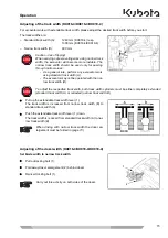
Spring adjustment (operator’s weight)

!

The seat can be set to the weight of the operator using the toggle (figure above, position/3). Refer to the
weight indicator (figure above, position/2) when choosing your setting.

!

Sit down on the operator’s seat.

!

Swivel the toggle outwards by 90°.

!

Pumping up and/or down,change the spring tension until the weight indicator shows your own weight.

Backrest adjustment

Take the load off the backrest and pull up the backrest adjustment lever (figure above, position/1). Set the backrest
to the desired sitting position and release the lever. The backrest should be adjusted so that the operator can safe-
ly operate the control levers with the back resting completely on the backrest.

Seat belt

!

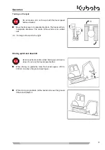
Buckle up.

!

Check that the seat belt is fastened tightly.

Rear view mirrors adjustment

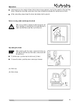
!

Check the adjustment of the rear view mirrors. If necessary, adjust the mirrors until the optimum sight is en-
sured.

Adjust the seat so that the arrow points to the centre of the weight indicator.

Do not operate the excavator without the seat belt fastened.

STOP

Summary of Contents for KX 016-4

Page 1: ...GB MINI EXCAVATOR MODELS KX015 4 KX016 4 KX018 4 KX019 4 OPERATING INSTRUCTIONS RG158 8135 6 Original 07 2014...

Page 2: ...usively valid contractual warranty refer to the Duties liability and warranty section page 13 This documentation does neither extend nor restrict the contractual warranty KUBOTA Baumaschinen GmbH rese...

Page 3: ...avator 18 Safety devices 25 Locking the controls 25 Engine stop knob 25 Protective structure canopy and cab 26 Emergency hammer 27 Locking of the swivel frame 27 Hazards coming from the hydraulic syst...

Page 4: ...ration 57 Safety rules for operation 57 Safety for children 58 Guiding the operator 58 Working in the vicinity of overhead power lines 59 Working in the vicinity of underground power lines 59 Initial...

Page 5: ...the dozer 79 Overview of control lever functions 80 Operating the boom 80 Operating the arm 81 Operating the bucket 81 Swivelling the swivel frame 82 Swinging the boom 83 Operating of the auxiliary p...

Page 6: ...ntenance 118 Safety rules for maintenance 118 Personnel requirements 118 Maintenance interval display 119 General maintenance chart 50 to 500 hours of operation 120 General maintenance chart 550 to 10...

Page 7: ...44 Tightening torque for hydraulic hoses 145 Tightening torque for hydraulic pipes 145 Tightening torque for hydraulic adapters 145 Recommended lubricants 146 Excavator repairs 147 Safety inspection 1...

Page 8: ...r example EMC electromagnetic compatibility EN European standard GL Ground level incl including ISO International Organization for Standardiza tion kg kilogramme km h kilometre per hour kN kilonewton...

Page 9: ...temperature Service interval indicator Swivel boom left Swivel boom right Dozer up Dozer down Control lever direction Control lever direction Rotary beacon Display selector switch Auxiliary port indic...

Page 10: ...Tables 10...

Page 11: ...d e g optional KX015 4 KX016 4 KX018 4 KX019 4 and KX019 4 SF The terms front and direction of travel refer to the view of the op erator when seated on the operator s seat Forward direction of travel...

Page 12: ...personnel Trained personnel are skilled persons with a technical qualification who are able to determine damages to the ex cavator and perform repairs in their area of qualification e g hydraulic or e...

Page 13: ...General information 13...

Page 14: ...may only be used for the approved use and in a completely safe operating state Malfunctions which can reduce safety must be repaired immediately Warranty and liability The scope period and form of the...

Page 15: ...formation which may not be immediately evident to the op erator Identifies operating procedures which must be followed exactly to prevent damage to the excavator or other property Identifies operating...

Page 16: ...the Approved use section page 15 of the excava tor documented in these operating instructions is considered an unapproved use This also applies to the non observance of the standards and guidelines l...

Page 17: ...ke sure that all operators and users have read and understood these operating instructions Persons who work with or on the excavator must be provided by the operator with and where applicable use suit...

Page 18: ...t the workplaces subject to actually existing conditions oth er noise sources special operating conditions sound reflections Depending on the actual noise emissions the owner must provide the necessar...

Page 19: ...excavator When staying in the danger zone and in the case of a suddenly starting excavator there is the danger of being run over by the excavator Only start the machine from the driver s seat Do not s...

Page 20: ...ing from rotating components The rotary fan can cut into the extremities Danger of squashing from rotating components The rotary belt drive can draw in limbs and squash them Do not reach into rotating...

Page 21: ...sults in severe injury or death Do not stay in the swivel area of the boom Ensure safety distance to obstacles and sufficient freedom of mo vement 3 Code RG138 5791 0 Danger of injury from components...

Page 22: ...Safety rules 21 1 Code RG109 5796 0 Not an attachment point for lifting gear 2 Code RG058 5749 0 KX015 4 KX016 4 cab 2 Code RG158 5749 0 KX018 4 KX019 4 cab 2 Code RG158 5759 0 KX019 4 SF cab...

Page 23: ...4 Canopy 1 Code RG158 5758 0 KX019 4 SF Canopy 2 Code RG308 5702 0 Risk of accidents by incorrect operation Improper operating can lead to damage to the excavator to serious ac cidents with high risk...

Page 24: ...be hot and lead to burns Apertures e g ventilation systems and hot components must not be covered with hands 2 Code RG138 5717 0 When using a wider or deeper bucket take good care when swinging or ret...

Page 25: ...step 2 Code RG158 5729 0 Risk of injury from falling front window If the front window has been pushed up and not is properly bolted the re is a risk that the front window will close automatically and...

Page 26: ...e control levers 3 and 6 on the right and left the drive levers 2 the boom swing pedal 1 and the dozer control lever 5 are not op erational when the console 7 is raised This circumstance allows safe g...

Page 27: ...474 1 Annex G e g tearing down walls the corresponding protective equipment is required e g gravel guard The excavator is equipped with a protective structure that protects the operator from severe in...

Page 28: ...ed with water and soap immediately if possible Do this thoroughly and repeatedly otherwise there is a risk of damage to the skin Immediately take off any clothes dirtied or soaked with hydraulic oil P...

Page 29: ...xhaust pipes and mufflers must be checked daily for leaks damage and any loose or missing joints Leaking or damaged exhaust system components must be replaced or repaired before starting up the machin...

Page 30: ...ble values for the towed load and the maximum pressing load vertical down on the towing eye during recovery see Specifications page 39 Safety rules while loading with a crane Crane and lifting gear mu...

Page 31: ...ort vehicle pull the parking brake and secure the invididual wheels of the transport vehicle at the front and rear respectively with chocks Secure the excavator against sliding on the transport vehicl...

Page 32: ...during excavation work sec tion page 78 Bring the boom in line with the longitudinal axis of the swivel frame Bucket cylinders and arm cylinders respectively must be extended up to the stop position...

Page 33: ...es 1 on each side of the boom As soon as the lifting gear is attached to the excavator press cloths between lifting gear and excavator to protect the excavator Always keep the machine level Be sure th...

Page 34: ...sport vehicle For securing the vehicle tie down the points as shown in the figure The corresponding eye bolts must be screwed in at the rear weight 2 pieces not included in the scope of delivery Adher...

Page 35: ...rm and bucket and lower the boom until the bucket linkage touches the loading area Secure the chains and the dozer with beams 2 Secure the excavator against sliding on the transport vehicle with chock...

Page 36: ...ription of the excavator 35 Description of the excavator Model overview The excavator is available in the model series KX015 4 KX016 4 KX018 4 and KX019 4 The figures show the versions with canopy and...

Page 37: ...19 4 can be found in the following illustra tions including tables Dimensions KX015 4 All dimensions in mm with original KUBOTA bucket and rubber crawlers A B C D E F G H I J K L KX015 4 450 510 990 1...

Page 38: ...0 2350 KX018 4 450 510 1300 990 1070 990 3450 2380 2380 1940 1480 2350 KX019 4 SF 450 510 1300 990 1100 990 3450 2380 2380 1940 1480 2350 KX019 4 450 510 1300 990 1100 990 3620 2580 2560 2140 1520 235...

Page 39: ...ption of the excavator 38 Arm version Name Type KX015 4 Arm 950 mm A 950 mm KX016 4 Arm 950 mm A 950 mm KX018 4 Arm 1090 mm A 1090 mm KX019 4 SF Arm 1090 mm A 1090 mm KX019 4 Arm 1190 mm A 1190 mm A A...

Page 40: ...1 Ground pressure without operator kPa kgf cm 24 5 0 25 25 5 0 26 25 5 0 26 26 5 0 27 Climbing performance degrees 27 15 27 15 Max lateral sway degrees 18 10 18 10 Dozer width x height mm 990 x 230 9...

Page 41: ...f cm 25 5 0 26 26 5 0 27 26 5 0 27 27 4 0 28 Climbing performance degrees 27 15 27 15 Max lateral sway degrees 18 10 18 10 Dozer width x height mm 990 1300 x 230 990 1300 x 230 Swing angle of the boom...

Page 42: ...ta in the field on the back of the front cover 1 CE marking 2 Serial 3 Max pulling capacity at the towing eyes 4 Max vertical load at the towing eyes 5 Product ID number PIN 6 Year of construction 7 E...

Page 43: ...g standard equipment Operating instructions with protective cover Spare parts catalogue Filter wrench Filler funnel for diesel fuel Grease gun Spare fuse 50 A Guarantee Spare parts catalogue and guara...

Page 44: ...l frame 2 Track frame 3 Cab 4 Operator s place 5 Cab door 6 Side cover 7 Drive sprocket 8 Crawler 9 Idler 10 Dozer enlargement 11 Dozer 12 Dozer cylinder 13 Swing block 14 Boom cylinder 15 Bucket 16 B...

Page 45: ...ck 2 Wrist rest 3 Left control lever Description of the components of the left control console 1 Control lever lock To enter and leave the cab the console must be raised by pulling up the control leve...

Page 46: ...KX015 4 KX016 4 KX018 4 Drive levers and control pedals description 1 Left and right drive levers With the drive levers the excavator can be driven forwards and backwards and also turned The left driv...

Page 47: ...Indicator Pull out key 14 Indicator Insert key 15 Travel speed indicator 16 Indicator Fuel stock 17 Indicator Pre glowing 18 Engine oil pressure indicator Description of the components of the right co...

Page 48: ...he air flow can be set to HIGH HI or LOW LO 9 Engine stop knob Using this device the operator can switch off the engine manually 10 Rotary beacon button The rotary beacon accessory is switched on with...

Page 49: ...g light The warning light flashes red when a system fault or technical malfunction occurs The warning light flashes yellow when the system issues a warning 10 Indicator Set clock If the clock needs ad...

Page 50: ...ts up when the oil pressure is below the reference value Other equipment at the operator s place Other equipment located at and around the operator s place is described below Interior lighting An inte...

Page 51: ...width of the excavator can be adjusted between standard track width A and narrow track width B for passing through nar row areas The track widths are The setting of the track width is with the contro...

Page 52: ...s on the left vehicle side under the side cover Return change valve for direct return flow According to mode of operation of a given attachment the return flow of the hydraulic oil must either be via...

Page 53: ...en refuelling Rear view mirror The rear view mirrors 1 allow for visibility to the rear The rear view mirrors can be adjusted for optimum visibility of the respective areas Heating and ventilation cab...

Page 54: ...in the cab With the lever 1 the air intake can be switched between recirculat ed air A and fresh air B The air is guided to the air nozzles 1 via the heat exchanger The heater valve 1 in the engine c...

Page 55: ...of the swivel frame it is covered by a lockable hinged cover 1 2 3 7 5 6 8 9 10 11 12 13 4 1 Coolant expansion reservoir 2 Water separator 3 Fuel filter 4 Fuel pump 5 Oil filler opening 6 Engine 7 Air...

Page 56: ...he dozer control lever controls the valve via a bowden cable The accumulator figure below 4 allows lowering the boom and the arm in the event of engine failure The hydraulic oil tank contains the suct...

Page 57: ...and oil cooler The coolant radiator and the oil cooler are located under the side cover 1 Coolant radiator 2 Oil cooler 3 Tank breather filter Do not unscrew the tank breather filter plug 4 The tank...

Page 58: ...n an angle which allows the operator to use the crawler or the step if applicable to enter the cab Always stop the engine when leaving the cab In exceptional cases e g for troubleshooting the cab can...

Page 59: ...e manoeuvring area Before leaving the machine park it so that it cannot move When leaving the machine e g for breaks or at the end of work stop the engine remove the key and close the cab door if pres...

Page 60: ...in the vicinity of underground power lines Before starting with excavation work the owner of the excavator or the person responsible for the work must check if there are any underground power lines i...

Page 61: ...tor switch 1 the follow ing are selected in this order year month day 12 or 24 hour indi cator hours and minutes for adjusting Press display selector switch 1 and hold down Press menu button 2 to redu...

Page 62: ...ional services Open the engine compartment cover page 107 Close engine compartment cover after completion of the ac tivities Open the side cover page 108 Always close the side cover after the work is...

Page 63: ...ge Replace the V belts if necessary page 126 Checking the exhaust system for leaks Check the exhaust system for leaks and security formation of cracks If the exhaust system is leaky or loose the excav...

Page 64: ...Position arm and bucket as shown in the figure Stop the engine page 70 Lubricate all greasing points see figure to the right see the Recommended lubricants section page 146 by injecting grease until f...

Page 65: ...page 78 Lubricate all greasing points with grease see the Recommended lubricants section page 146 until fresh grease emerges Checking the electric cables and connections Check all accessible electric...

Page 66: ...le 2 up as far as possible by pulling the control lever lock 1 up Get into the excavator use the chain as a stepping aid Sit down on the operator s seat The fuel gauge 1 indicates the relative fuel am...

Page 67: ...ackrest and pull up the backrest adjustment lever figure above position 3 Set the backrest to the desired sitting position and release the lever The backrest should be adjusted so that the op erator c...

Page 68: ...st and pull up the backrest adjustment lever figure above position 1 Set the backrest to the desired sitting position and release the lever The backrest should be adjusted so that the operator can saf...

Page 69: ...rols are in the neutral position Starting the excavator is only allowed when the operator is sitting on the operator s seat Before starting the engine make the necessary operator station adjustments p...

Page 70: ...e indicator 2 blinks yellow there is only a little fuel is left in the tank refuel excavator page 103 Turn the starter switch to the START position and hold it there until the engine has started Relea...

Page 71: ...e engine oil pressure becomes too low during operation the en gine must be stopped immediately The engine oil pressure indica tor 1 lights up the warning light 2 flashes red and the display message as...

Page 72: ...ose to full capacity the temperature of the coolant can rise a little higher than normal The indicator Coolant temperature 1 blinks and the message appears in the display as shown in the figure on the...

Page 73: ...the engine immediately if the engine speed rises or drops suddenly abnormal noises are heard the excavating devices do not respond to the control lever as expected or the exhaust fumes are black or wh...

Page 74: ...2 behind dozer Reinsert locking bolt 1 Standard track width A 1240 mm KX016 4 resp 1300 mm KX018 4 KX019 4 Narrow track width B 990 mm Caution risk of tipping When carrying out excavating work using...

Page 75: ...s and indicators page 70 When working on slopes observe the tilt of the excavator see fig ure Climbing performance 27 resp 15 Max lateral sway 18 resp 10 Keep the bucket as low as possible when drivin...

Page 76: ...Select an appropriate engine speed Driving Push both drive levers forward simultaneously to drive the excavator straight ahead Releasing the drive le vers stops the excavator immediately To reverse t...

Page 77: ...the right drive lever in neutral push the left drive lever forward In this case the turning radius is determined by the right track A The excavator makes a right turn Do not drive fast on muddy or une...

Page 78: ...the right Driving uphill and downhill When driving on gradients raise the bucket approx 200 to 400 mm A above the ground see figure When driving on gradients let the bucket slide over the ground if t...

Page 79: ...t use the dropping action of the bucket for excavation Never fully extend the cylinders Always keep a certain safety margin especially when operating with a break er accessory Never use the bucket as...

Page 80: ...he ground Note on using wider and deeper buckets Operating the dozer To lift the dozer pull the dozer control lever 1 back To lower the dozer push the dozer control lever forward A Dozer up B Dozer do...

Page 81: ...ntrol lever forward fig ure The boom moves as shown in the figure Control lever Movement Right control lever 1 Lower boom 2 Raise boom 3 Bucket crowd 4 Bucket dump Left control lever A Arm crowd B Arm...

Page 82: ...he left control lever back figure The arm moves as shown in the figure Operating the bucket To crowd digging the bucket move the right control lever to the left figure To dump empty the bucket move th...

Page 83: ...control lever to the left fig ure To turn clockwise move the left control lever to the right fig ure The turning operation takes place as shown in the figure No person is allowed to stand in the swive...

Page 84: ...y to be worn safety shoes safety helmet eye protection ear protection and if necessary facial mask The use of a gravel guard front protective grid is recommended For excavation work with a cab the fro...

Page 85: ...to be worn safety shoes safety helmet eye protection ear protection and if necessary facial mask The use of a gravel guard front protective grid is recommended For excavation work with a cab the fron...

Page 86: ...cker switch in direction A The oil will flow towards connector A on the right side of the arm Move the auxiliary port 1 rocker switch in direction B The oil will flow towards connector B on the left s...

Page 87: ...peration has been selected the set flow rate in the right auxiliary port connector and then in the left auxiliary port connector is indicated for few seconds in the display 2 by pressing the display s...

Page 88: ...adjust the optimum flow rates for the new implement Turn the starter switch to the RUN position Press menu button 2 The display message as in the figure on the right appears Press display selector sw...

Page 89: ...e setting changes to left AUX port After setting the flow rate for the operating mode selected you can either switch to the next operating mode or exit the settings screen To change the operating mode...

Page 90: ...reen toggles between mode 1 and mode 2 and the default display screen When the flow rate setting value is set to Zero for both AUX ports in a certain operating mode this operating mode will not be ind...

Page 91: ...he en gine run Selecting the operating mode Moving the arrow marking Selection of symbols Yes No No Yes Setting the maximum flow rate Setting the maximum flow rate Enable Auxiliary Port lit up flashin...

Page 92: ...in the figure depending on the action of the implement being used ro tary or breaking Pressure relief of the hydraulic system Lower front attachments and dozer completely Turn the starter switch to t...

Page 93: ...flashes The set flow rate in the right auxiliary port connector and then in the left auxiliary port connector is indicated for few seconds in the dis play by pressing the display selector switch 1 If...

Page 94: ...xcavator if necessary page 103 Close and lock the cab door The key must remain with the operator Check the excavator for external damage and for leaks Any defects must be repaired before the next star...

Page 95: ...longer operation of the heat er the aerial supply should be switched back to position fresh air 3 after the warm up phase of the cab is complete The heater valve should be always closed in summer All...

Page 96: ...a longer period of time can lead to lack of oxygen and overheating inside the cab No cool fresh air flows in from the outside The operator therefore overtires quickly Risk of injury If you turn on the...

Page 97: ...rter switch is in the RUN position Press the switch 2 to the ON position The interior light 1 is illuminated as long as the switch remains in this position To switch off press the switch 2 to the OFF...

Page 98: ...Opening the cab door from outside Unlock the cab door at the door lock 3 Open the cab door by pulling at the door handle 1 and lock the door by attaching the hook 2 at the cab wall Closing the cab doo...

Page 99: ...re above 1 simultaneously and using both grips figure above 2 push the front window forward within the guide rails up to the stopper Lock the front window at the stopper by re leasing the lock bars Ch...

Page 100: ...lock snaps in at the window frame Operating the working lights optional for KX015 4 KX016 4 The starter switch is in the RUN position Press the working light button 1 to the ON position The work ing l...

Page 101: ...hite lubricant Grease the cab door hinges Fill the washer system with a antifreeze window cleaner page 103 Operation during the winter season The excavator must be cleaned after work is finished page...

Page 102: ...ck if the charge lamp turns off after starting Disconnect the jumper cable at the frame of the excavator first and then at the negative terminal of the helping vehicle Disconnect the second jumper cab...

Page 103: ...ilure or if malfunctions occur in the hydraulic system The starter switch is in the RUN position If necessary lower the boom and the arm with the control levers as described in the Operating the contr...

Page 104: ...n open flame or other sources of ignition are not allowed The danger zone has to be clearly marked with signs A fire extinguisher must be kept at hand in the danger zone Spilled fuel must be bound imm...

Page 105: ...ng signals are output Interrupted signal Tank is empty Periodic signal Tank is being filled Continuous signal Tank is full Press switch 1 after refuelling to deactivate fill level monitoring Bleeding...

Page 106: ...in the figure below Defective fuses may only be replaced with fuses of the same type and same rating The bypassing of fuses for example by a wire is not allowed If the malfunction can not be remedied...

Page 107: ...5 A 13 Control unit 5 A 3 Fuel pump 5 A 14 Engine cut off switch 30 A 4 Control unit AC 10 A 15 12 V socket 15 A 5 Relay supply circuit 5 A 16 Wiper washer system 15 A 6 Alternator 10 A 17 Radio AC 15...

Page 108: ...wered functions will also be switched off e g horn fuel fill level monitor etc The user settings for the display and control unit are saved and the battery discharges itself only minimally Risk of inj...

Page 109: ...e catch has snapped into place prop erly If the engine cover is unexpectedly slammed shut for example by another person or by the wind serious injury could result Make sure that the lock has properly...

Page 110: ...that the indicator light is illuminated when leaving the machine The vehicle comes with two different types of keys Black individual key This key is used to start the engine The engine can be started...

Page 111: ...osition again or the key is removed within this time period When a key registered for this machine is inserted into the starter switch the acoustic signal will be turned off Do not use several of thes...

Page 112: ...vicinity of the excavator by briefly honking the horn Make sure that all operational controls are in the neutral position Starting the excavator is only allowed when the operator is sitting on the op...

Page 113: ...position RUN to complete the registration process 9 One after the other insert all registered black keys into the starter switch and check whether the engine can be started using these keys Do not tu...

Page 114: ...tor must always be ensured If troubleshooting of the excavator calls for the bucket being raised the operator may not stand in the area of the front attachments unless the front attachments are secure...

Page 115: ...ection of ex cavator Crawler tension adjusted incorrectly Check and adjust the crawler tensi on if necessary page 139 No pilot controlled hydraulic func tions available Fuse in fuse box defective Repl...

Page 116: ...the maintenance proce dure 4 Period check passed warning This message means that the reg ular service is due The machine can be operated but service must be carried out urgently Ask your KUBOTA deale...

Page 117: ...n the V belt is OK let the engine run until indicator goes out If the indicator does not go out inform your KUBOTA deal er immediately 17 Fuel sensor error red The fuel sensor has developed a fault th...

Page 118: ...can be operated but the auxil iary port will not func tion Inform your KUBOTA dealer im mediately 23 Auxiliary port 1 system error red Auxiliary port 1 has developed a fault The machine can be operat...

Page 119: ...starting by removal of the key The bucket must always be lowered to the ground for servicing The bucket must always be lowered to the ground for servicing When defects are detected during servicing or...

Page 120: ...urs of operation Interval 50 100 250 500 600 750 1000 1 C 001 Engine oil change 500 h 2 C 002 Hydraulic oil change 1000 h 3 C 003 Replace the air filter elements 1000 h 4 C 004 Replace the fuel filter...

Page 121: ...lt daily 62 Check the fluid level of the washer system reservoir daily 103 Check the electric cables and connections daily 64 Cleaning of coolant radiator and oil cooler daily 125 Lubricate the front...

Page 122: ...belt daily 62 Check the fluid level of the washer system reservoir daily 103 Check the electric cables and connections daily 64 Cleaning of coolant radiator and oil cooler daily 125 Lubricate the fron...

Page 123: ...and adjust the V belt 250 h 126 Change the engine oil and oil filter 500 h 127 Replace the drive unit oil 3 500 h 140 Replace the fuel filter 500 h 130 Replace the return filter 2 500 h 132 Change lin...

Page 124: ...filter 500 h 127 Replace the drive unit oil 3 500 h 140 Replace the fuel filter 500 h 130 Replace the return filter 2 500 h 132 Change line filter 1000 h 142 Replace the auxiliary valve fil ter 1000...

Page 125: ...pansion reservoir cap when the engine is cool and fill pre mixed coolant up to the FULL mark 1 Close the expansion tank cover If the coolant expansion reservoir was completely empty check the coolant...

Page 126: ...de cover page 108 Clean coolant radiator 1 and oil coolers 2 from the engine with a water jet or a compressed air gun Do not use high pres sure cleaners Particular care must be devoted to the space be...

Page 127: ...ne compartment cover page 107 Inspect all hose connections on the engine and to the radiator or to the heater fan cab version for condition cracks bulges hard spots tightness and firm seating of the c...

Page 128: ...2 adding coolant if necessary page 124 Close the engine compartment and side cover Replacing the engine oil and oil filter Open the engine compartment cover page 107 Fill the coolant in a container an...

Page 129: ...ee the Recom mended lubricants section page 146 Screw in the oil filler cap Start the engine page 68 The engine oil pressure indicator must go out as soon as the engine has started If this does not ha...

Page 130: ...damaged or too much dust has accumulated on it Clean the outer filter element with compressed air max 5 bar from the inside out without damaging the filter element Wear eye protection for this service...

Page 131: ...ing the water separator Open the engine compartment cover page 107 Turn the cock 3 to the OFF position Unscrew retainer 1 while holding on to the cup 2 Remove the cup Dispose of cleaning cloths accord...

Page 132: ...nscrew the drain plug 2 Open the drain valve 1 by turning to position B and drain the water Close the drain valve by turning to position A Screw the drain plug back in Checking the fuel lines and the...

Page 133: ...free cloth Install a new filter and tighten it by hand Insert the return filter page 132 Fill hydraulic oil page 134 Pay attention to utmost cleanliness when servicing the hydraulic system This servic...

Page 134: ...s and dozer down to the bottom as shown in the figure Stop the engine Open bottom plate 1 Pay attention to utmost cleanliness when servicing the hydraulic system This service may only be carried out a...

Page 135: ...nge approx 14 2 L Total hydraulic system capacity 27 L Remove the filler plug 1 from the hydraulic oil tank Insert a clean funnel with a strainer into the filler plug opening Fill hydraulic oil to hal...

Page 136: ...id under all circumstances If clothing skin or eyes have come in contact with battery acid rinse the affected parts immediately with water If the eyes are affected immediately seek medical attention N...

Page 137: ...d take off the cable clamp Put the clamp to the side so that contact with the negative terminal is excluded Remove the plus terminal cover and take off the cable clamp Put the clamp to the side so tha...

Page 138: ...ame 360 several times to distribute the grease evenly Grease at each 90 position of the swivel gear Fill a to tal of approx 50 g of grease approx 20 shots with the grease gun Refer to the Recommended...

Page 139: ...ozer as shown in the figure Stop the engine remove the key Refer to the Op erating the controls during excavation work section page 78 Lubricate all greasing points with grease see the Recommended lub...

Page 140: ...sion The crawler seam 1 is half way between the idler and sprock et Check the crawler sag as shown in the figure Crawler sag A 10 15 mm If the crawler sag is more than 25 mm adjust the crawler If nece...

Page 141: ...re below position 2 is positioned at the bottom Place a catch tray with a minimum capacity of 2 L under the drain plug Remove the drain plug and let the oil drain completely Install the drain plug wit...

Page 142: ...ter must be replaced Cleaning Clean the filter 1 with compressed air in direction A oppo site the normal direction of flow Insert fresh air filter Insert safety pin Close the side cover page 108 If th...

Page 143: ...lose the engine compartment and side cover Changing the Line Filter Release the pilot circuit pressure Raise the LH control console 1 Remove the lower trim panels Remove the hydraulic line white Unscr...

Page 144: ...se the pilot circuit pressure Remove the floor mat Remove the right hand bottom plate 1 Remove the hydraulic line 2 Unscrew the line filter 3 Screw in a new filter Reinstall the hydraulic line Replace...

Page 145: ...14 107 9 125 5 11 0 12 8 123 6 147 1 12 6 15 0 166 7 196 1 17 0 20 0 M 16 166 7 191 2 17 0 19 5 196 1 225 6 20 0 23 0 259 9 304 0 26 5 31 0 M 20 333 4 392 3 34 0 40 0 367 7 431 5 37 5 44 0 519 8 568...

Page 146: ...Torque in Nm Pipe size Thread 17 30 35 6x1 M12x1 5 17 30 35 8x1 M14x1 5 19 40 45 10x1 5 M16x1 5 22 60 65 12x1 5 M18x1 5 27 75 80 15x1 5 M22x1 5 30 90 100 16x2 M24x1 5 32 110 120 18x2 M26x1 5 36 130 14...

Page 147: ...stem G048 SAE J1034 MB 325 0 ASTM D3306 D4985 ROWE Hightec Anti freeze AN 37 C Only use distilled wa ter for mixing and ob serve the mixing ta ble of the respective manufacturer Grease NLGI 2 DIN 5182...

Page 148: ...check particular attention must be paid to the repaired parts and the safety devices Fuel ASTM D975 EN 590 The machine is deliv ered with summer die sel In winter fill up with diesel fuel for winter...

Page 149: ...st not be influenced by personal economic or company interests The inspection is a visual and functional check of all components for condition and complete ness and of the effectiveness of the safety...

Page 150: ...ent bearing capacity for the weight of the excavator The storage place must be frost free dry and well ventilated Measures before taking out of service Clean and dry the excavator thoroughly page 124...

Page 151: ...ston rods of the hydraulic cylinders Install the battery page 136 Check the safety devices for proper operation Carry out the pre operational services page 61 If defects are detected during start up r...

Page 152: ...ion only For more information see chapter Accessories section KUBOTA Pipe safety valve page 161 The lifting attachment is to be attached to the implement or to other parts of the excavator in such a m...

Page 153: ...ver the maximum permissible lifting capacity is not allowed The values given in the tables apply only to level and hard grounds When working on soft ground the machine can tip over easily as the load...

Page 154: ...Lifting capacity of the excavator 153 Max lifting load during swivel operation is 360 KX015 4 KX016 4 cab arm 950 mm KX018 4 KX019 4 cab arm 1090 mm and arm 1190 mm...

Page 155: ...Lifting capacity of the excavator 154 KX019 4 SF cab arm 1090 mm KX015 4 KX016 4 canopy arm 950 mm...

Page 156: ...Lifting capacity of the excavator 155 KX018 4 KX019 4 canopy arm 1090 mm and arm 1190 mm KX019 4 SF canopy arm 1090 mm...

Page 157: ...0 28 500 5 4 0 55 3 8 0 39 2 9 0 30 GL 0 4 7 0 48 5 3 0 54 3 8 0 39 2 8 0 29 500 5 3 0 54 7 0 0 71 4 8 0 49 3 4 0 35 1000 8 5 0 87 5 9 0 60 4 0 0 41 2 8 0 29 1500 4 3 0 44 2 8 0 29 2000 2500 MODEL KX...

Page 158: ...0 28 500 5 4 0 55 3 8 0 39 2 9 0 30 GL 0 4 7 0 48 5 3 0 54 3 8 0 39 2 8 0 29 500 5 3 0 54 7 0 0 71 4 8 0 49 3 4 0 35 1000 8 5 0 87 5 9 0 60 4 0 0 41 2 8 0 29 1500 4 3 0 44 2 8 0 29 2000 2500 MODEL KX...

Page 159: ...4 0 0 41 3 1 0 32 GL 0 6 1 0 62 5 8 0 59 4 1 0 42 3 1 0 32 500 5 9 0 60 7 9 0 81 5 3 0 54 3 8 0 39 2 8 0 29 1000 9 1 0 93 6 8 0 69 4 5 0 46 3 2 0 33 1500 11 4 1 16 5 2 0 53 3 4 0 35 2000 2500 MODEL KX...

Page 160: ...0 55 5 7 0 58 4 0 0 41 3 0 0 31 2 4 0 24 500 5 3 0 54 7 7 0 79 5 2 0 53 3 8 0 39 2 8 0 29 1000 7 8 0 80 6 8 0 69 4 5 0 46 3 3 0 34 2 4 0 24 1500 11 0 1 12 5 5 0 56 3 6 0 37 2 5 0 26 2000 2500 MODEL KX...

Page 161: ...0 0 41 3 1 0 32 GL 0 6 1 0 62 5 8 0 59 4 1 0 42 3 1 0 32 500 5 9 0 60 7 9 0 81 5 3 0 54 3 8 0 39 2 8 0 29 1000 9 1 0 93 6 8 0 69 4 5 0 46 3 2 0 33 1500 11 4 1 16 5 2 0 53 3 4 0 35 2000 2500 MODEL KX0...

Page 162: ...nder 1 or dozer cylinder 3 Excavators that will be used in the lifting operation must be equipped with at least a pipe safety valve on the boom and arm to gether with an overload warning function acco...

Page 163: ...ators that will be used in the lifting operation must be equipped with at least a pipe safety valve on the boom and arm to gether with an overload warning function according to EN 474 5 An additional...

Page 164: ...er KUBOTA Foot pedal kit The foot pedal kit 1 allows the operator to foot control the drive le vers 2 The functions of the left and or right foot pedal correspond to the left and or right drive levers...

Page 165: ......

Reviews: