ASSEMBLY
OM 0427SBC-A
12
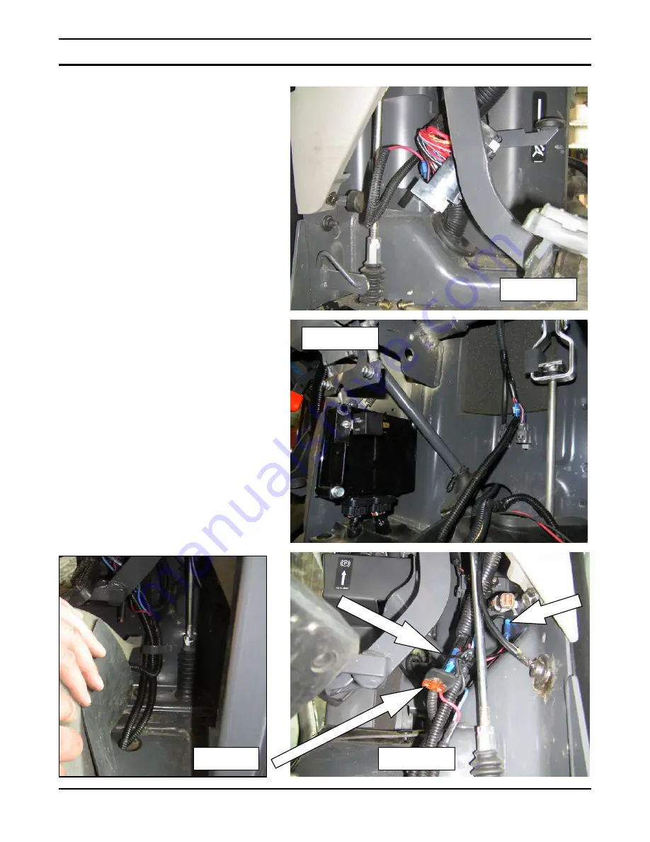
4. Figures 3-3a:
Find a wire in the
back of the fuse holder which is a
power supply source "key on
signal"; that means that when the
ignition key is in the ON position, the
power gets through. Install the green
wire to this wire with the supplied
tap connector. If the fuse holder is
hard to reach, you can use a wire
from the right side of the dash (see
figure 3a).
5. Figure 4:
The electric harness is
made to facilitate installation; there
are junctions at different locations.
Pass the wires previously installed
so they do not get in the way of the
operator. Reconnect the wire
junctions to their related color.
6. Figure 4-5:
Push the wires under the
console making sure to keep an easy
access to the fuse holder. Run the
red and blue wires under the step
plate to reach the switch for
connection.
Figure 3
Figure 4
Figure 5
Figure 3a
Summary of Contents for L4474
Page 33: ...ELECTRICAL DIAGRAM OM 0427SBC A 31 ELECTRICAL DIAGRAM ...
Page 36: ...PARTS OM 0427SBC A 34 SNOWBLOWER FIG 000200_RAD1511015 ...
Page 38: ...PARTS OM 0427SBC A 36 SNOWBLOWER CONT D FIG 000300_RAD1511016 ...
Page 42: ...PARTS OM 0427SBC A 40 HYDRAULIC SYSTEM FIG 000600_RAD1511018 ...
Page 52: ...Printed in Canada ...


