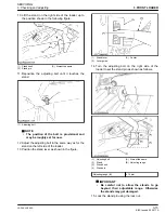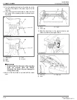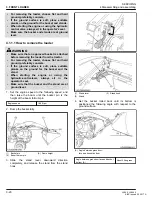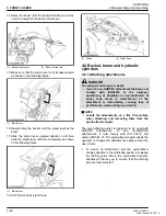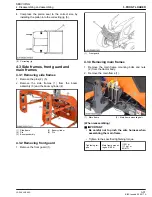
8. When pushing the quick-attach-coupler-handles
into the
locked
position, visually verify that the latch
pins rotate completely and are located underneath
the stop of the quick attach coupler.
(1) Latch pins
(2) Quick attach coupler stopper
9. When attaching different attachments, visually
inspect for broken or damaged pins. If broken or
damaged pins are found, replace before using.
Use of broken pins may result in detachment or
deformation of the attachment, causing loss of
performance, personal injury, or death.
You are now ready to use the attached attachment.
Attach and remove all compatible attachments using
the same method.
WARNING
To avoid personal injury, death, or machine damage
• Never operate or transport the attachments
which are not attached properly.
• Always replace damaged hardware immediately.
4.2.2 Detaching attachments
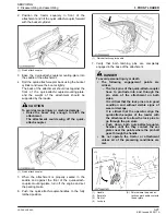
Detach the attachments in the reverse procedure of
attaching the attachments.
1. Lower the attachment to ground level with the
attachment slightly in the rolled back position.
2. Stop the engine and set the parking brake.
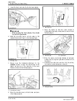
3. Pull the quick-attach-coupler-handles to the
unlatched position to release the latching pins.
4. While sitting in the operator's seat of the tractor,
start the engine and slowly move the loader-control-
lever to the dump position until the attachment is
pushed away slightly from the quick-attach-coupler.
5. Lower the boom of the loader so that the quick-
attach-coupler-mounting-plate
clears
the
attachment saddle.
6. Back away from the attachment slowly.
7. If an attachment is not going to be attached to the
quick-attach-coupler immediately, push the quick-
attach-coupler-handles to the locked position to
prevent damage to the handle assembly.
4.2.3 Removing bucket cylinder
CAUTION
To avoid personal injury:
• Before you disconnect hydraulic hoses, be sure
to release all pressure.
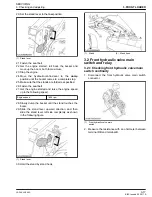
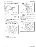
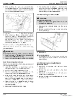
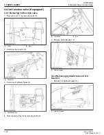
1. Disconnect the hydraulic hoses from the bucket
cylinder.
2. Remove lower pin and upper pin and remove the
bucket cylinder (1).
(1) Bucket cylinder
(When reassembling)
• To install the bucket cylinder (1), the hydraulic port
must point inside and be careful of the direction of
grease fittings.
4.2.4 Removing boom cylinder and
hydraulic tubes
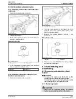
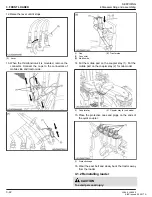
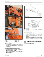
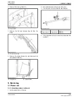
1. Disconnect the hydraulic hoses from the boom
cylinders (4).
2. Remove the pins (2) and remove the boom
cylinders (4).
3. Disconnect the hydraulic hoses (6) with quick
couplers at the control valve.
4. Remove the pins (1) and remove the boom (3) from
the side frame (5).
3. FRONT LOADER
SERVICING
4.Disassembling and assembling
3-28
LA344, LA344S
KiSC issued 02, 2017 A
Summary of Contents for LA344
Page 1: ...LA344 LA344S WORKSHOP MANUAL FRONT LOADER KiSC issued 02 2017 A ...
Page 5: ...1 INFORMATION KiSC issued 02 2017 A ...
Page 9: ...1 INFORMATION SAFETY FIRST 1 4 LA344 LA344S KiSC issued 02 2017 A ...
Page 11: ...1 INFORMATION SAFETY DECALS 1 6 LA344 LA344S KiSC issued 02 2017 A ...
Page 12: ...SAFETY DECALS 1 INFORMATION LA344 LA344S 1 7 KiSC issued 02 2017 A ...
Page 15: ...1 INFORMATION TERMINOLOGY 1 10 LA344 LA344S KiSC issued 02 2017 A ...
Page 20: ...2 GENERAL KiSC issued 02 2017 A ...
Page 22: ...2 GENERAL IDENTIFICATION 2 2 LA344 LA344S KiSC issued 02 2017 A ...
Page 24: ...2 GENERAL 2 4 LA344 LA344S KiSC issued 02 2017 A ...
Page 26: ...2 GENERAL LUBRICATING SYSTEM 2 6 LA344 LA344S KiSC issued 02 2017 A ...
Page 30: ...2 GENERAL TIGHTENING TORQUES 5 Hydraulic fittings 2 10 LA344 LA344S KiSC issued 02 2017 A ...
Page 32: ...2 GENERAL MAINTENANCE CHECK LIST 2 12 LA344 LA344S KiSC issued 02 2017 A ...
Page 36: ...2 GENERAL SPECIAL TOOLS 1 Special tools for loader 2 16 LA344 LA344S KiSC issued 02 2017 A ...
Page 37: ...3 FRONT LOADER KiSC issued 02 2017 A ...
Page 71: ...3 FRONT LOADER SERVICING 5 Servicing 3 34 LA344 LA344S KiSC issued 02 2017 A ...


