INDEX
Symbols
3rd function solenoid valve
checking connector voltage............................... 3-19
checking continuity.............................................3-19
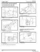
3rd function valve
removing............................................................ 3-32
structure............................................................... 3-7
A
acid burns
prevent................................................................. 1-3
activation switch
off position............................................................3-8
on position............................................................3-9
adapters..................................................................... 2-9
attachment
attaching............................................................ 3-26
detaching........................................................... 3-28
auto lock attachment and detachment
function................................................................ 3-6
outline.................................................................. 3-5
axial force...................................................................2-3
B
before you start service..............................................1-1
bolts........................................................................... 2-7
boom cylinder
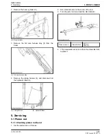
removing............................................................ 3-28
structure............................................................... 3-4
bucket
specifications......................................................1-11
bucket cylinder
removing............................................................ 3-28
structure............................................................... 3-4
C
circlip..........................................................................2-3
control lever
operating..............................................................3-3
correcting jig.............................................................2-15
cylinder head
removing............................................................ 3-29
D
daily checking
loader.................................................................2-13
danger, warning, and caution labels.......................... 1-8
dimensional specification......................................... 1-12
E
elbows........................................................................2-9
emergencies
preparation...........................................................1-3
F
fire.............................................................................. 1-2
fluids correctly
discarding.............................................................1-3
force........................................................................... 2-3
front guard
removing............................................................ 3-31
front hydraulic valve main switch
checking connector voltage............................... 3-18
checking continuity.............................................3-17
front loader
tightening torques.............................................. 3-13
troubleshooting...................................................3-11
front remote hydraulic control system........................ 3-3
G
grease........................................................................ 2-3
grease fittings.............................................................2-8
H
height of loader stand
adjusting.............................................................3-14
hydraulic circuit.......................................................... 3-1
hydraulic tube
removing............................................................ 3-28
L
loader
identification......................................................... 2-1
lubricating...........................................................2-13
reinstall...............................................................3-23
remove............................................................... 3-20
specifications......................................................1-11
terminology.......................................................... 1-9
M
main frame
removing............................................................ 3-31
main frame bolt
checking torque..................................................2-14
re-tightening....................................................... 2-13
main frame nut
checking torque..................................................2-14
re-tightening....................................................... 2-13
mechanical loader frame
structure (standing mechanism)...........................3-6
LA344, LA344S
I
KiSC issued 02, 2017 A
Summary of Contents for LA344
Page 1: ...LA344 LA344S WORKSHOP MANUAL FRONT LOADER KiSC issued 02 2017 A ...
Page 5: ...1 INFORMATION KiSC issued 02 2017 A ...
Page 9: ...1 INFORMATION SAFETY FIRST 1 4 LA344 LA344S KiSC issued 02 2017 A ...
Page 11: ...1 INFORMATION SAFETY DECALS 1 6 LA344 LA344S KiSC issued 02 2017 A ...
Page 12: ...SAFETY DECALS 1 INFORMATION LA344 LA344S 1 7 KiSC issued 02 2017 A ...
Page 15: ...1 INFORMATION TERMINOLOGY 1 10 LA344 LA344S KiSC issued 02 2017 A ...
Page 20: ...2 GENERAL KiSC issued 02 2017 A ...
Page 22: ...2 GENERAL IDENTIFICATION 2 2 LA344 LA344S KiSC issued 02 2017 A ...
Page 24: ...2 GENERAL 2 4 LA344 LA344S KiSC issued 02 2017 A ...
Page 26: ...2 GENERAL LUBRICATING SYSTEM 2 6 LA344 LA344S KiSC issued 02 2017 A ...
Page 30: ...2 GENERAL TIGHTENING TORQUES 5 Hydraulic fittings 2 10 LA344 LA344S KiSC issued 02 2017 A ...
Page 32: ...2 GENERAL MAINTENANCE CHECK LIST 2 12 LA344 LA344S KiSC issued 02 2017 A ...
Page 36: ...2 GENERAL SPECIAL TOOLS 1 Special tools for loader 2 16 LA344 LA344S KiSC issued 02 2017 A ...
Page 37: ...3 FRONT LOADER KiSC issued 02 2017 A ...
Page 71: ...3 FRONT LOADER SERVICING 5 Servicing 3 34 LA344 LA344S KiSC issued 02 2017 A ...

