FRONT LOADER
LA525, LA765, WSM
1-M6
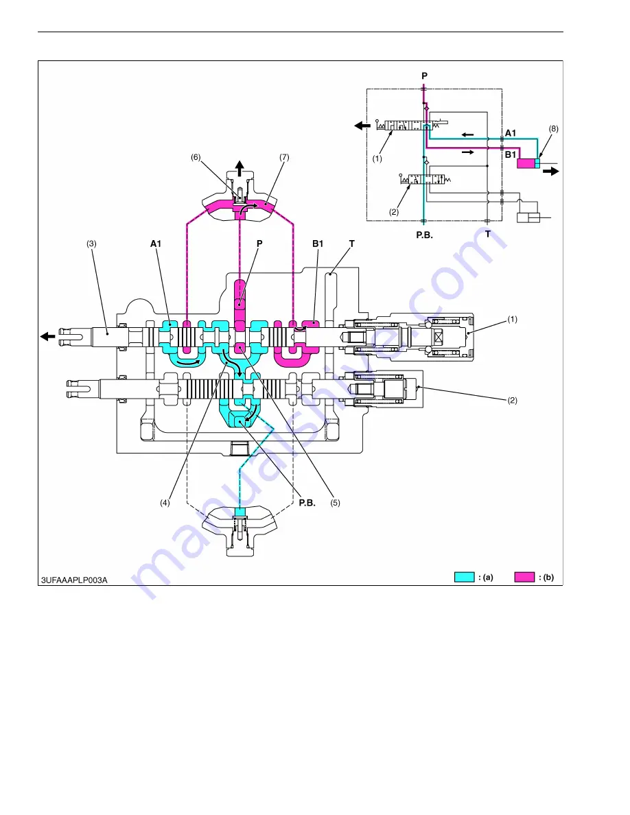
(2) Up
1. When the hydraulic control lever is set to the
"UP"
position, the spool (3) of the boom control section (1) moves
to the left. This makes oil passages between passage 1 (7) and
B1
port, also between
A1
port and
PB
passage
1 (4).
2. As the oil passage from the neutral passage 1 (5) to the
PB
passage 1 (4) is closed by the spool (3), the
pressure-fed oil from the
P
port opens the load check valve (6) and flows through the notched section of the spool
(3) and
B1
port to extend the boom cylinder (8).
3. Return oil from the boom cylinder (8) flows from the
A1
port through the passage in the spool (3) and
PB
passage
1 (4) to the bucket control section (2).
9Y1211014FLM0006US0
(1) Boom Control Section
(2) Bucket Control Section
(3) Spool
(4)
PB
Passage 1
(5) Neutral Passage 1
(6) Load Check Valve
(7) Passage 1
(8) Boom Cylinder
P:
P Port
T:
T Port
A1: A1 Port
(From Boom Cylinder)
B1: B1 Port (To Boom Cylinder)
PB: PB Port
(a) Low Pressure
(b) High Pressure
KiSC issued 06, 2017 A
Summary of Contents for LA525
Page 1: ...LA525 LA765 WORKSHOP MANUAL FRONT LOADER KiSC issued 06 2017 A ...
Page 4: ...I INFORMATION KiSC issued 06 2017 A ...
Page 10: ...INFORMATION LA525 LA765 WSM I 5 9Y1211014INI0001US0 KiSC issued 06 2017 A ...
Page 11: ...INFORMATION LA525 LA765 WSM I 6 9Y1211014INI0002US0 KiSC issued 06 2017 A ...
Page 20: ...G GENERAL KiSC issued 06 2017 A ...


