FRONT LOADER
LA525, LA765, WSM
1-S24
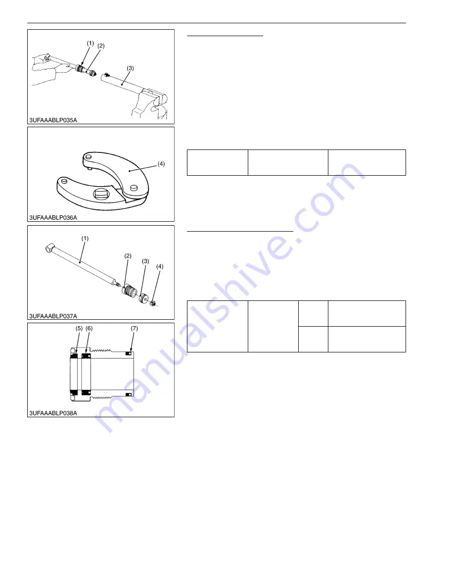
Piston Rod Assembly
1. Drain hydraulic oil from the cylinder, and hold the tube end of the
cylinder in a vise.
2. Remove the cylinder head (1) with the adjustable gland nut
wrench (4).
3. Pull out the piston rod assembly (2) from the cylinder tube (3).
(When reassembling)
• Visually examine the cylinder tube for signs of scoring or
damage.
• Put the piston rod assembly to the cylinder tube. Be careful not
to damage the piston seal on the piston.
• Install the cylinder head to the cylinder tube. Be careful not to
damage the O-ring on the cylinder head.
9Y1211014FLS0019US0
Cylinder Head, Piston and Nut
1. Hold the rod end in a vise.
2. Remove the nut (4), and remove the piston (3) and cylinder
head (2) from the piston rod (1).
(When reassembling)
• Visually examine all parts for signs of scoring or damage.
• Put the piston rod to the cylinder head. Be careful not to damage
the wiper seal (5) and oil seal (6).
9Y1211014FLS0020US0
Tightening torque
Cylinder head
200 to 230 N·m
20.4 to 23.5 kgf·m
145 to 169 lbf·ft
(1) Cylinder Head
(2) Piston Rod Assembly
(3) Cylinder Tube
(4) Adjustable Gland Nut Wrench
Tightening torque
Boom and
bucket cylinder
piston mounting
nut
LA525
150 to 180 N·m
15.3 to 18.3 kgf·m
111 to 132 lbf·ft
LA765
200 to 230 N·m
20.4 to 23.5 kgf·m
147 to 170 lbf·ft
(1) Piston Rod
(2) Cylinder Head
(3) Piston
(4) Nut
(5) Wiper Seal
(6) Oil Seal
(7) O-ring
KiSC issued 06, 2017 A
Summary of Contents for LA525
Page 1: ...LA525 LA765 WORKSHOP MANUAL FRONT LOADER KiSC issued 06 2017 A ...
Page 4: ...I INFORMATION KiSC issued 06 2017 A ...
Page 10: ...INFORMATION LA525 LA765 WSM I 5 9Y1211014INI0001US0 KiSC issued 06 2017 A ...
Page 11: ...INFORMATION LA525 LA765 WSM I 6 9Y1211014INI0002US0 KiSC issued 06 2017 A ...
Page 20: ...G GENERAL KiSC issued 06 2017 A ...


