FRONT LOADER
LA525, LA765, WSM
1-S30
(6) Side Frame, Main Frame and Others (LA765)
Side Frame
1. Remove the loader assembly from loader main frame (See
page 1-S13.)
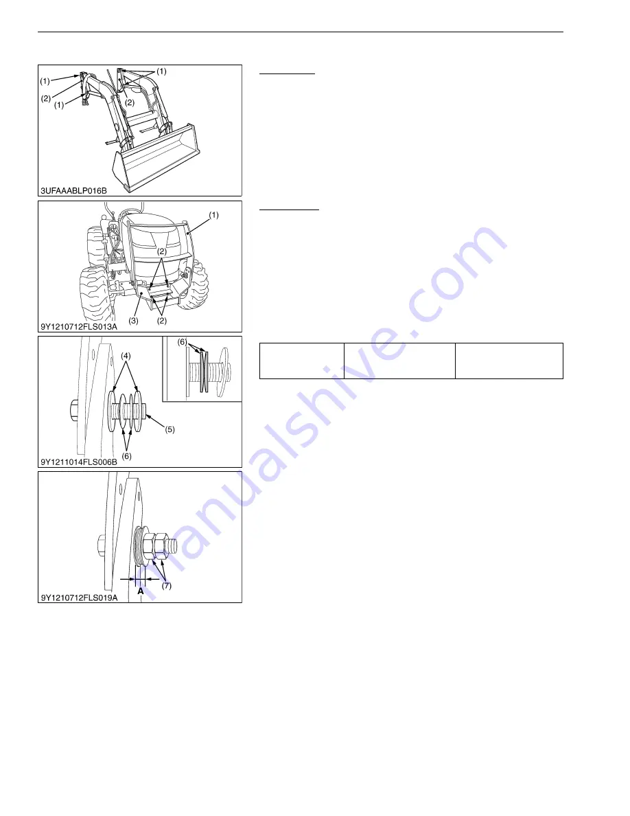
2. Remove the pins (1) and remove the side frames (2) from the
boom.
9Y1211014FLS0023US0
Front Guard
1. Remove the pivot bolts (5), unlock the front guard lever.
2. Remove the upper front guard (1).
3. Remove the front guard mounting bolt (2) and remove the lower
front guard (3) from front axle frame.
(When reassembling)
• Assemble the pivot bolts (5), Plain washers (4) and plate
springs (6) as shown in the figure.
• Make sure the plate springs (6) are in the specified direction as
shown in the figure.
• Set the space
"A"
to the specified value.
9Y1211014FLS0027US0
(1) Pin
(2) Side Frame
Tightening torque
Front guard mounting bolt
and nut
124 to 147 N·m
12.6 to 15.0 kgf·m
91.2 to 108 lbf·ft
(1) Upper Front Guard
(2) Front Guard Mounting Bolt (M14)
(3) Lower Front Guard
(4) M20 Plain Washer (Large)
(5) Pivot Bolt
(6) M20 Plate Spring
(7) M20 Hex. Nut
A: 12 to 13 mm (0.47 to 0.51 in.)
KiSC issued 06, 2017 A
Summary of Contents for LA525
Page 1: ...LA525 LA765 WORKSHOP MANUAL FRONT LOADER KiSC issued 06 2017 A ...
Page 4: ...I INFORMATION KiSC issued 06 2017 A ...
Page 10: ...INFORMATION LA525 LA765 WSM I 5 9Y1211014INI0001US0 KiSC issued 06 2017 A ...
Page 11: ...INFORMATION LA525 LA765 WSM I 6 9Y1211014INI0002US0 KiSC issued 06 2017 A ...
Page 20: ...G GENERAL KiSC issued 06 2017 A ...


