171
HYDRAULIC UNIT
C
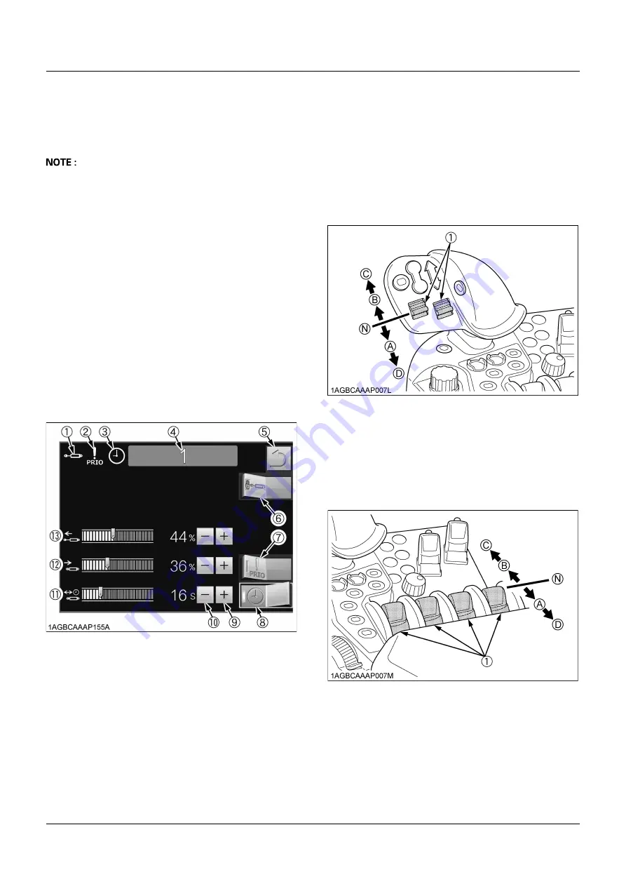
Flow rate and timer
The flow rate in both directions of the remote control
cylinders and their operating time can be preset (timer-
controlled).
A
First set the switch to the "EXTEND" or "RETRACT"
position. Then release your hand, and the timer starts
counting. When the time is over, the oil feed to the
implement is stopped.
From now on, the timer can be preset with the switch
alone.
If the switch is held at the "EXTEND" or "RETRACT"
position, the oil feed is continued even after the timer
has stopped counting.
A
When the switch or the lever is operated in the
opposite way, the timer counting is cancelled.
A
When the timer and detent function are used together,
the valve can serve as a double-acting valve with
detents and self canceling.
C
Securing the priority flow
Oil is preferentially fed from the hydraulic pump to a
specified remote control valve.
Once the priority flow is ensured, the indicator (2) lights
up.
B
Remote Control Valve Switch
The remote control valve switches direct pressurized oil
flow to the implement hydraulic system.
C
Use of remote valves 1 and 2
Each switch can be set at 5 positions.
If the switch is held at the FLOAT or DETENT position, the
switch is held at that position.
C
Use of remote valves 3 to 6
Each switch can be set at 5 positions.
(1) Remote control valve operating status indicator
(2) Priority flow status indicator
(3) Automatic shut-off timer indicator
(4) Remote control valve number
(5) Previous screen resume switch
(6) Remote control valve lock/unlock switch
(7) Priority flow status on/off switch
(8) Automatic shut-off timer on/off switch
(9) Plus (+) switch
(10) Minus (-) switch
(11) Automatic shut-off timer control
(12) Discharge rate from cylinder (retract) control
(13) Discharge rate from cylinder (extend) control
(1) Remote control valve switch
(A) "EXTEND"
(B) "RETRACT"
(N) "NEUTRAL"
(C) "FLOAT"
(D) "DETENT"
(1) Remote control valve switch
(A) "EXTEND"
(B) "RETRACT"
(N) "NEUTRAL"
(C) "FLOAT"
(D) "DETENT"
Summary of Contents for M7131
Page 16: ......
Page 24: ...SAFE OPERATION 8 7 DANGER WARNING AND CAUTION LABELS ...
Page 25: ... 9 SAFE OPERATION ...
Page 26: ...SAFE OPERATION 10 ...
Page 27: ... 11 SAFE OPERATION ...
Page 28: ...SAFE OPERATION 12 ...
Page 29: ... 13 SAFE OPERATION ...
Page 30: ...SAFE OPERATION 14 ...
Page 32: ......
Page 41: ...9 IMPLEMENT LIMITATIONS Hitch made by SCHARMÜLLER ...
Page 66: ...INTELLIPANEL TM CONTROL 34 1 Screen selector switch ...
Page 166: ...OPERATING THE TRACTOR 134 1 Field out button 2 Field in button 3 Indicator ...


