8-S6
M8540, M9540, WSM
HYDRAULIC SYSTEM
4. CHECKING AND ADJUSTING
[1] HYDRAULIC PUMP
Hydraulic Flow Test
IMPORTANT
Q
• When using flowmeter other than KUBOTA specified
flowmeter, be sure to use the instructions with the
flowmeter.
• Do not close the flowmeter loading valve completely, before
testing, because it has no relief valve.
• Set the main change lever and shuttle lever in Neutral
position.
• Set parking brake lever in parking position.
1. Place the disassembling stand under the transmission case.
2. Remove the right rear wheel.
3. Place the disassembling stand under the right rear axle case.
4. Disconnect the differential lock rod from pedal.
5. Disconnect the delivery pipe for power steering or delivery pipe
for 3 point hydraulic from hydraulic pump (2).
6. Install the adaptor
53
and
54
(refer to “SPECIAL TOOLS” at “G.
GENERAL” section) to the pump discharge port.
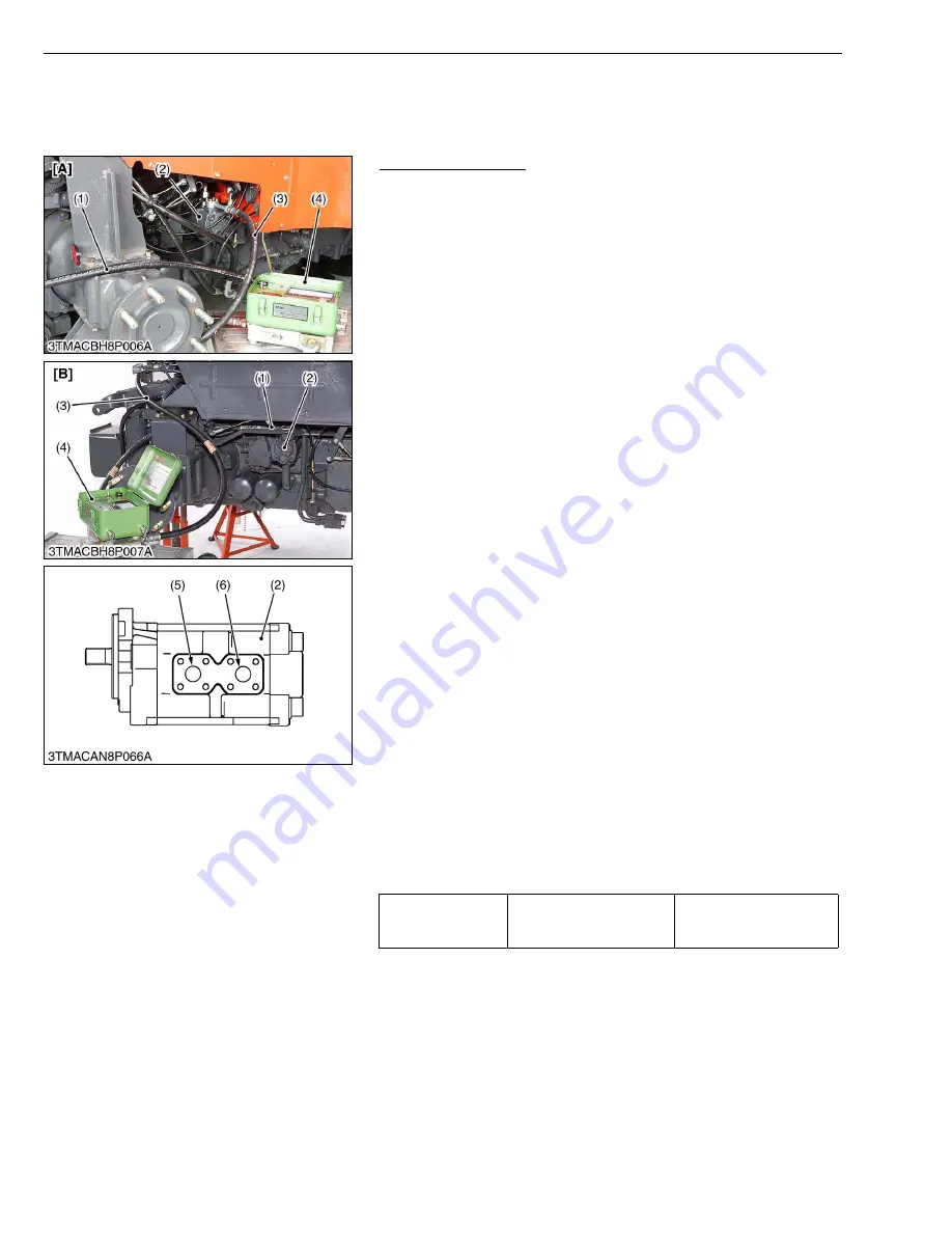
7. Connect the hydraulic test hose (3) to the adaptor at hydraulic
pump (2) and flowmeter (4) inlet port.
8. Connect the other hydraulic test hose (1) to the flowmeter outlet,
insert the hydraulic test hose other end to transmission oil filling
port at PTO case.
9. Open the flowmeter loading valve completely. (Turn
counterclockwise.)
10.Start the engine and set the engine speed at 2000 to 2200 min
-1
(rpm).
11.Slowly close the loading valve to generator pressure approx. 9.8
MPa (100 kgf/cm
2
, 1422 psi). Hold in this condition until oil
temperature reaches approx. 55 °C (131 °F).
12.Open the loading valve completely.
13.Set the engine speed. (Refer to
“Condition”
.)
14.Read and note the pump delivery at rated pressure.
15.Open the loading valve completely and stop the engine.
16.If the pump delivery does not reach the allowable limit, check the
pump suction line, oil filter or hydraulic pump.
17.Check the hydraulic flow test for power steering and three point
pump are same procedure.
(When reassembling)
W1010684
Tightening torque
Rear wheel mounting nut
343 to 401 N·m
35.0 to 41.0 kgf·m
254 to 297 lbf·ft
(1) Hydraulic Test Hose
(2) Hydraulic Pump
(3) Hydraulic Test Hose
(4) Flowmeter
(5) Port for 3-Point Hydraulic
(6) Port for Power Steering
[A] ROPS Model
[B] CABIN Model
KiSC issued 09, 2008 A
Summary of Contents for M9540
Page 1: ...M8540 M9540 WORKSHOP MANUAL TRACTOR KiSC issued 09 2008 A...
Page 8: ...6 M8540 M9540 WSM SAFETY INSTRUCTIONS KiSC issued 09 2008 A...
Page 9: ...7 M8540 M9540 WSM SAFETY INSTRUCTIONS KiSC issued 09 2008 A...
Page 10: ...8 M8540 M9540 WSM SAFETY INSTRUCTIONS Q CABIN Model KiSC issued 09 2008 A...
Page 11: ...9 M8540 M9540 WSM SAFETY INSTRUCTIONS KiSC issued 09 2008 A...
Page 12: ...10 M8540 M9540 WSM SAFETY INSTRUCTIONS KiSC issued 09 2008 A...
Page 16: ...14 M8540 M9540 WSM DIMENSIONS DIMENSIONS ROPS Model KiSC issued 09 2008 A...
Page 17: ...15 M8540 M9540 WSM DIMENSIONS CABIN Model KiSC issued 09 2008 A...
Page 18: ...G GENERAL KiSC issued 09 2008 A...
Page 103: ...1 ENGINE KiSC issued 09 2008 A...
Page 203: ...2 CLUTCH KiSC issued 09 2008 A...
Page 219: ...3 TRANSMISSION KiSC issued 09 2008 A...
Page 322: ...4 REAR AXLE KiSC issued 09 2008 A...
Page 323: ...CONTENTS MECHANISM 1 FEATURES 4 M1 KiSC issued 09 2008 A...
Page 336: ...5 BRAKES KiSC issued 09 2008 A...
Page 374: ...6 FRONT AXLE KiSC issued 09 2008 A...
Page 401: ...7 STEERING KiSC issued 09 2008 A...
Page 402: ...CONTENTS MECHANISM 1 STEERING MECHANISM 7 M1 2 STEERING CYLINDER 7 M2 KiSC issued 09 2008 A...
Page 420: ...8 HYDRAULIC SYSTEM KiSC issued 09 2008 A...
Page 473: ...9 ELECTRICAL SYSTEM KiSC issued 09 2008 A...
Page 554: ...10 CABIN KiSC issued 09 2008 A...


