43
THREE-POINT HITCH & DRAWBAR
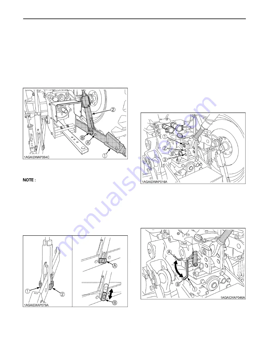
3-POINT HITCH
B
Selecting the holes of Lower Links
There are two holes in the lower links. For most
operations the lifting rods should be attached to the (B)
hole.
A
The lifting rods may be attached to (A) for greater
lifting force.
B
Adjusting Lateral Float
To allow the implement to follow ground contour, attach
the rectangular washers and pin heads in vertical position.
To hold the implement, reset the rectangular washers and
pin heads in horizontal position.
C
Floating mechanism
When the floating mechanism is used, the implement is
able to follow the tractor freely in response to the soil and
ground conditions. This is suited for operation with
implements wider than the tractor.
B
Selecting the Top Link Mounting Holes
Select the proper set of holes by referring to the
"Hydraulic Control Unit Use Reference Chart" in Hydraulic
Unit section.
If the hydraulic unit is set for draft control, draft response
is more sensitive when an implement is connected to the
lower set of top link mounting holes. If draft control is not
required, it is recommended to use the top set (1).
B
Draft Stopper
To reduce the vibrations of attachments, set the draft
stopper to the "LOCK" position.
When using the draft control for plowing and similar
works, set the draft stopper to the "UNLOCK" position.
1
.
Make preparations for attaching
implement.
(1) Lower link
(2) Lifting rod
holes: (A), (B)
(1) Rectangular washer
(2) Pin head
(A) Horizontal position
(B) Vertical position
(1) Draft stopper
(A) "LOCK"
(B) "UNLOCK"
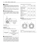
Summary of Contents for M96SDTM
Page 10: ......
Page 17: ... 7 SAFE OPERATION 7 DANGER WARNING AND CAUTION LABELS ...
Page 18: ...SAFE OPERATION 8 ...
Page 19: ... 9 SAFE OPERATION ...
Page 20: ...SAFE OPERATION 10 ...
Page 21: ... 11 SAFE OPERATION ...
Page 121: ...M96SDTM MUDDER TRACTOR M96SDTM ...
Page 124: ......


