ME8200DTN, WSM
FRONT AXLE
N6-S12
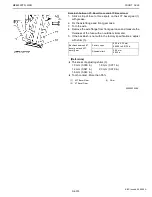
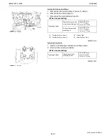
Differential Gear
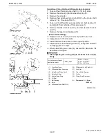
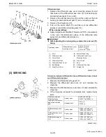
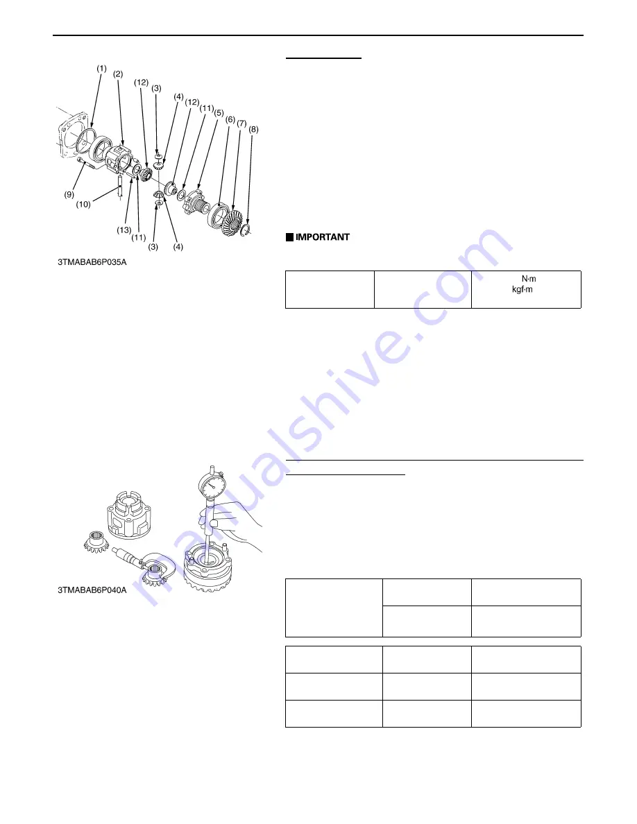
1. Remove the differential case cover mounting screws (9) and
then take out the differential case cover (5), ball bearing (6)
and spiral bevel gear (7) as a unit.
2. Remove the external snap ring (8), and then remove the ball
bearing (6) and spiral bevel gear (7) as a unit with a puller.
3. Remove the straight pin (13).
4. Pull out the pinion shaft (10) and take out the differential
pinions (4) and differential side gears (12).
(When reassembling)
A
Apply molybdenum disulfide (Three Bond 1901 or equivalent)
to the inner circumferential surface of the differential side
gears (12) and differential pinions (4).
A
After adjusting the turning torque stake the lock nut (11)
firmly.
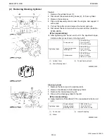
[3] SERVICING
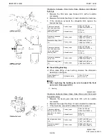
Clearance between Differential Case (Differential Case Cover)
and Differential Side Gear
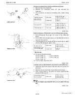
1. Measure the differential side gear O.D..
2. Measure the differential case bore I.D. and calculate the
clearance.
3. Measure the differential case cover bore I.D. and calculate the
clearance.
4. If the clearance exceeds the allowable limit, replace faulty
parts.
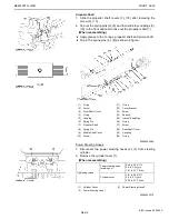
Tightening torque
Differential case cover
mounting screw
60.8 to 70.6
6.2 to 7.2
44.8 to 52.1 ft-lbs
(1)
Shim
(8)
External Snap Ring
(2)
Differential Case
(9)
Differential Case Cover
(3)
Thrust Collar
Mounting Screw
(4)
Differential Pinion
(10)
Pinion Shaft
(5)
Differential Case Cover
(11)
Shim
(6)
Ball Bearing
(12)
Differential Side Gear
(7)
Spiral Bevel Gear
(13)
Straight Pin
0000001915E
Clearance between
differential case
(differential case cover)
and differential side
gear
Factory spec.
0.040 to 0.123 mm
0.00157 to 0.00484 in.
Allowable limit
0.20 mm
0.0079 in.
Differential case bore
I.D.
Factory spec.
32.000 to 32.062 mm
1.25984 to 1.26228 in.
Differential case cover
bore I.D.
Factory spec.
32.000 to 32.062 mm
1.25984 to 1.26228 in.
Differential side gear
O.D.
Factory spec.
31.939 to 31.960 mm
1.25744 to 1.25827 in.
0000001921E
KiSC issued 04, 2006 A
Summary of Contents for ME8200DTN
Page 1: ...WORKSHOP MANUAL TRACTOR ME8200DTN SUPPLEMENT KiSC issued 04 2006 A...
Page 7: ...ME8200DTN WSM SAFETY INSTRUCTIONS N5 0000003126E KiSC issued 04 2006 A...
Page 8: ...ME8200DTN WSM SAFETY INSTRUCTIONS N6 0000003588E KiSC issued 04 2006 A...
Page 9: ...ME8200DTN WSM SAFETY INSTRUCTIONS N7 0000003589E KiSC issued 04 2006 A...
Page 11: ...ME8200DTN WSM DIMENSIONS N9 DIMENSIONS 0000003590E KiSC issued 04 2006 A...
Page 12: ...NG GENERAL KiSC issued 04 2006 A...
Page 33: ...N1 ENGINE KiSC issued 04 2006 A...
Page 42: ...N2 CLUTCH KiSC issued 04 2006 A...
Page 43: ...CONTENTS 1 TRAVELLING CLUTCH N2 M1 KiSC issued 04 2006 A...
Page 57: ...N3 TRANSMISSION KiSC issued 04 2006 A...
Page 102: ...N4 REAR AXLE KiSC issued 04 2006 A...
Page 103: ...CONTENTS 1 STRUCTURE N4 M1 KiSC issued 04 2006 A...
Page 113: ...N5 BRAKES KiSC issued 04 2006 A...
Page 114: ...CONTENTS 1 STRUCTURE N5 M1 KiSC issued 04 2006 A...
Page 124: ...N6 FRONT AXLE KiSC issued 04 2006 A...
Page 125: ...CONTENTS 1 STRUCTURE N6 M1 KiSC issued 04 2006 A...
Page 144: ...N7 STEERING KiSC issued 04 2006 A...
Page 150: ...N8 HYDRAULIC SYSTEM KiSC issued 04 2006 A...
Page 179: ...N9 ELECTRICAL SYSTEM KiSC issued 04 2006 A...
Page 180: ...CONTENTS 1 WIRING DIAGRAM N9 M1 2 COLOR OF WIRING N9 M2 KiSC issued 04 2006 A...

