ME8200DTN, WSM
HYDRAULIC SYSTEM
N8-S15
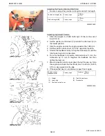
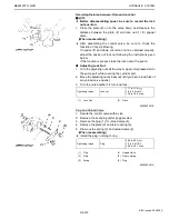
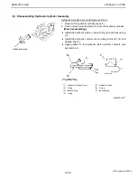
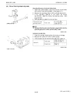
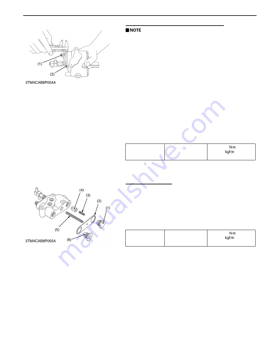
Recording Distance between Plate and Lock Nut
A
Before disassembling spool, be sure to record the lock
nut position.
1. Press the plate (2) on to the valve body, and measure the
distance between the plate (2) and lock nut (1) for poppet
valve.
(When reassembling)
A
After assembling the control valve, be sure to check the
function of it by air-blowing.
If neutral, lift and down circuit can not be obtained properly,
adjust the position of lock nut following the instructions given
below.
If the function is proper, stake the lock nut with a punch.
B
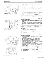
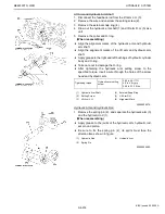
Adjusting Lock Nut
1. Turn the adjusting nuts all the way in, apply compressed air to
the pump port while covering the cylinder port.
2. Move the adjusting nuts slowly out until you hear a loud hiss of
air (unload valve opens).
3. Turn the nuts another 1/4 turn and lock.
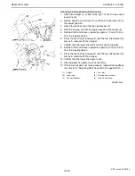
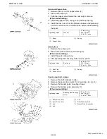
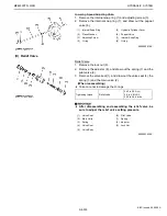
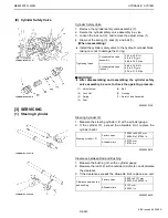
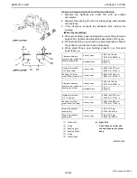
Plug and Unload Valve
1. Secure the control valve with a vise.
2. Remove the seat plug (6) for poppet valve.
3. Remove the plug (1) for unload valve (4).
4. Remove the plate (2) and return spring (5).
5. Draw out the spring (3) and unload valve (4).
(When reassembling)
A
Install the plug, nothing O-ring.
Tightening torque
Lock nut
17.7 to 21.6
1.8 to 2.2
13.0 to 15.9 ft-lbs
(1)
Lock Nut
(2)
Plate
0000003627E
Tightening torque
Plug
68.6 to 88.3
7.0 to 9.0
50.6 to 65.1 ft-lbs
(1)
Plug
(4)
Unload Valve
(2)
Plate
(5)
Return Spring
(3)
Spring
(6)
Plug
0000003581E
KiSC issued 04, 2006 A
Summary of Contents for ME8200DTN
Page 1: ...WORKSHOP MANUAL TRACTOR ME8200DTN SUPPLEMENT KiSC issued 04 2006 A...
Page 7: ...ME8200DTN WSM SAFETY INSTRUCTIONS N5 0000003126E KiSC issued 04 2006 A...
Page 8: ...ME8200DTN WSM SAFETY INSTRUCTIONS N6 0000003588E KiSC issued 04 2006 A...
Page 9: ...ME8200DTN WSM SAFETY INSTRUCTIONS N7 0000003589E KiSC issued 04 2006 A...
Page 11: ...ME8200DTN WSM DIMENSIONS N9 DIMENSIONS 0000003590E KiSC issued 04 2006 A...
Page 12: ...NG GENERAL KiSC issued 04 2006 A...
Page 33: ...N1 ENGINE KiSC issued 04 2006 A...
Page 42: ...N2 CLUTCH KiSC issued 04 2006 A...
Page 43: ...CONTENTS 1 TRAVELLING CLUTCH N2 M1 KiSC issued 04 2006 A...
Page 57: ...N3 TRANSMISSION KiSC issued 04 2006 A...
Page 102: ...N4 REAR AXLE KiSC issued 04 2006 A...
Page 103: ...CONTENTS 1 STRUCTURE N4 M1 KiSC issued 04 2006 A...
Page 113: ...N5 BRAKES KiSC issued 04 2006 A...
Page 114: ...CONTENTS 1 STRUCTURE N5 M1 KiSC issued 04 2006 A...
Page 124: ...N6 FRONT AXLE KiSC issued 04 2006 A...
Page 125: ...CONTENTS 1 STRUCTURE N6 M1 KiSC issued 04 2006 A...
Page 144: ...N7 STEERING KiSC issued 04 2006 A...
Page 150: ...N8 HYDRAULIC SYSTEM KiSC issued 04 2006 A...
Page 179: ...N9 ELECTRICAL SYSTEM KiSC issued 04 2006 A...
Page 180: ...CONTENTS 1 WIRING DIAGRAM N9 M1 2 COLOR OF WIRING N9 M2 KiSC issued 04 2006 A...

