1-S50
MX5100, WSM
ENGINE
Pistons
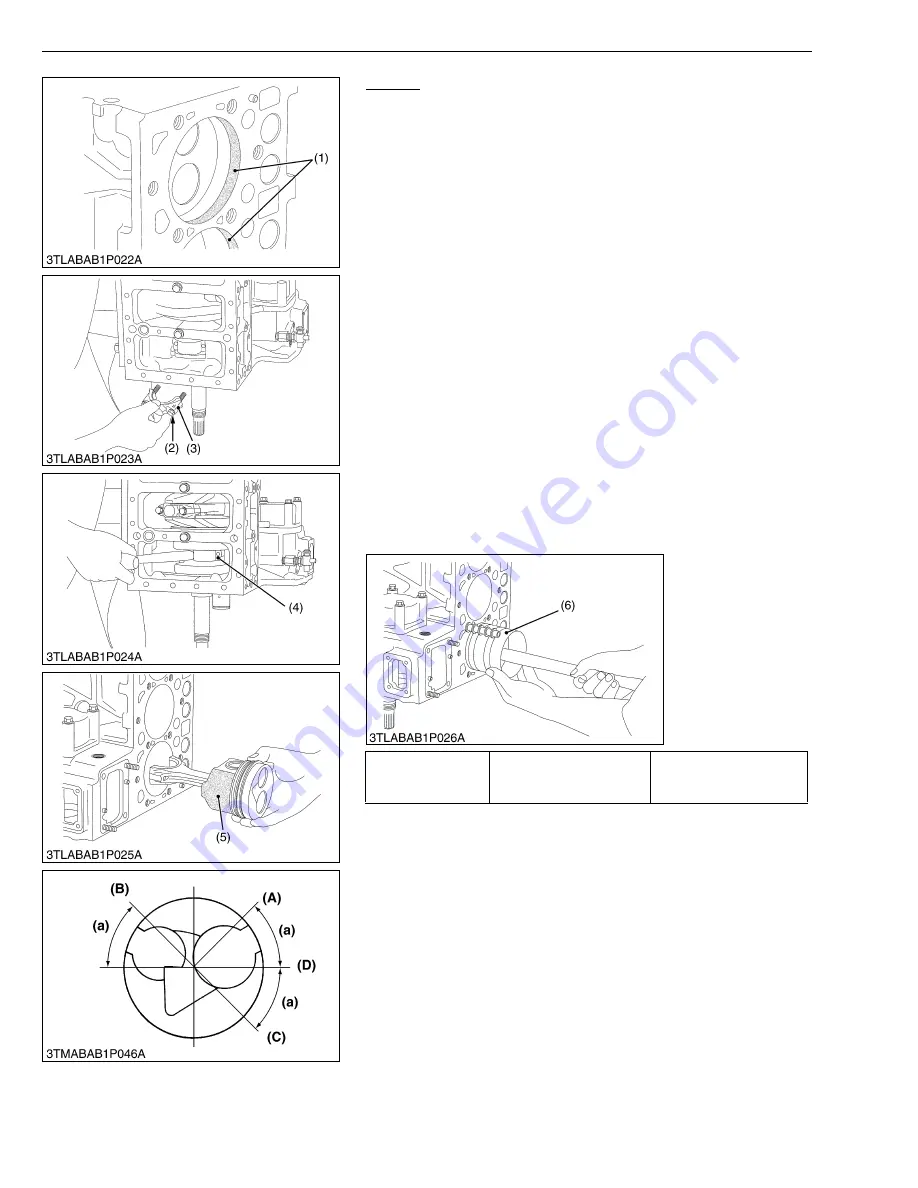
1. Completely clean carbon (1) in the cylinders.
2. Remove the connecting rod cap (3).
3. Turn the flywheel and bring the piston to top dead center.
4. Draw out the piston upward by lightly tapping it from the bottom
of the crankcase with the grip of a hammer.
5. Draw out the other piston in the same method as above.
(When reassembling)
• Before inserting piston into the cylinder, apply enough engine oil
to the piston.
• When inserting the piston into the cylinder, face the mark on the
connecting rod to the injection pump.
IMPORTANT
■
• Do not change the combination of cylinder and piston. Make
sure of the position of each piston by marking. For example,
mark “1” on the No. 1 piston.
• Place the piston rings with their gaps at 0.79 rad (45 °) from
the piston pin’s direction as shown in the figure.
• Carefully insert the pistons using a piston ring compressor
(6).
• When inserting the piston in place, be careful not to get the
molybdenum disulfide coating torn off its skirt. This coating
is useful in minimizing the clearance with the cylinder liner.
Just after the piston pin has been press-fitted, in particular,
the piston is still hot and the coating is easy to peel off. Wait
until the piston cools down.
W1026141
Tightening torque
Connecting rod screw
45 to 49 N·m
4.5 to 5.0 kgf·m
33 to 36 lbf·ft
(1) Carbon
(2) Connecting Rod Screw
(3) Connecting Rod Cap
(4) Connecting Rod
(5) Molybdenum Disulfide Coating in
Piston Skirt
(6) Piston Ring Compressor
(A) Top Ring Gap
(B) Second Ring Gap
(C) Oil Ring Gap
(D) Piston Pin Hole
(a) 0.79 rad (45 °)
Summary of Contents for MX5100
Page 2: ......
Page 8: ...6 MX5100 WSM SAFETY INSTRUCTIONS...
Page 9: ...7 MX5100 WSM SAFETY INSTRUCTIONS...
Page 12: ...10 MX5100 WSM DIMENSIONS DIMENSIONS...
Page 13: ...11 MX5100 WSM DIMENSIONS...
Page 14: ...12 MX5100 WSM DIMENSIONS...
Page 15: ...G GENERAL...
Page 16: ......
Page 18: ......
Page 87: ...1 ENGINE...
Page 88: ......
Page 90: ......
Page 92: ......
Page 166: ...1 S74 MX5100 WSM ENGINE...
Page 167: ...2 CLUTCH...
Page 168: ......
Page 170: ......
Page 174: ...2 M4 MX5100 WSM CLUTCH...
Page 176: ......
Page 205: ...3 TRANSMISSION...
Page 206: ......
Page 208: ......
Page 209: ...3 M1 MX5100 WSM TRANSMISSION 1 STRUCTURE 1 2WD...
Page 210: ...3 M2 MX5100 WSM TRANSMISSION 2 4WD...
Page 218: ......
Page 265: ...4 REAR AXLE...
Page 266: ......
Page 267: ...CONTENTS MECHANISM 1 STRUCTURE 4 M1...
Page 268: ......
Page 270: ...4 M2 MX5100 WSM REAR AXLE...
Page 272: ......
Page 278: ...4 S6 MX5100 WSM REAR AXLE...
Page 279: ...5 BRAKES...
Page 280: ......
Page 281: ...CONTENTS MECHANISM 1 STRUCTURE 5 M1...
Page 282: ......
Page 286: ......
Page 296: ...5 S10 MX5100 WSM BRAKES...
Page 297: ...6 FRONT AXLE...
Page 298: ......
Page 300: ......
Page 306: ......
Page 327: ...7 STEERING...
Page 328: ......
Page 330: ......
Page 334: ...7 M4 MX5100 WSM STEERING...
Page 336: ......
Page 355: ...8 HYDRAULIC SYSTEM...
Page 356: ......
Page 358: ......
Page 374: ......
Page 402: ...8 S28 MX5100 WSM HYDRAULIC SYSTEM...
Page 403: ...9 ELECTRICAL SYSTEM...
Page 404: ......
Page 406: ......
Page 407: ...9 M1 MX5100 WSM ELECTRICAL SYSTEM 1 WIRING DIAGRAM...
Page 420: ......
Page 454: ...9 S34 MX5100 WSM ELECTRICAL SYSTEM...


