2-S25
MX5100, WSM
CLUTCH
[3] SERVICING
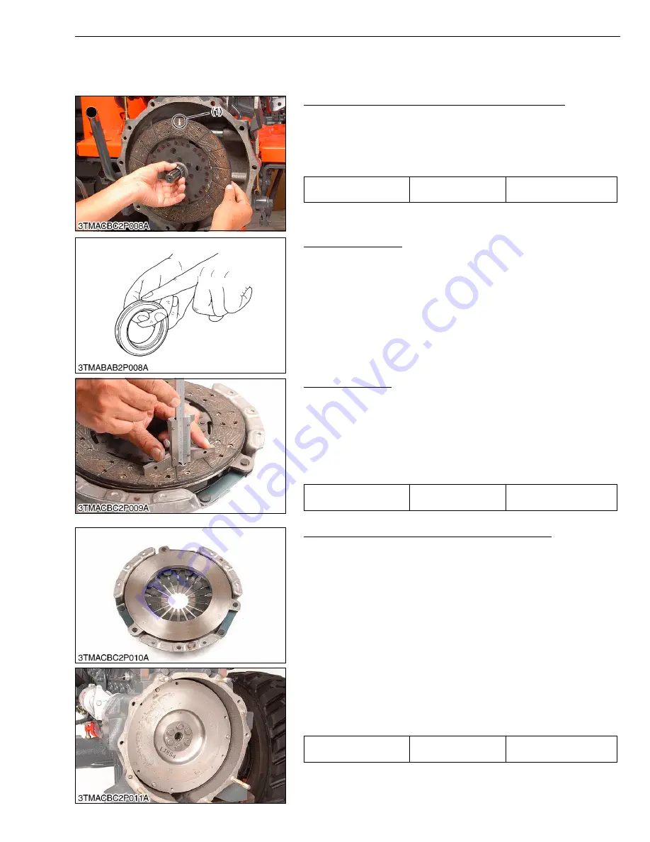
(1) Travelling Clutch
Backlash between Clutch Disc Boss and Gear Shaft
1. Mount the clutch disc to the gear shaft.
2. Hold the gear shaft so that it may not turn.
3. Rotate disc lightly and measure the displacement around the disc
edge.
4. If the measurement exceeds the allowable limit, replace the disc.
W10299170
Thrust Ball Bearing
1. Remove the thrust ball bearing from release hub with a puller.
2. Check for abnormal wear on contact surface.
3. Hold bearing inner race and rotate outer race, while applying
pressure to it.
4. If the bearing rotation is rough or noisy, replace the bearing.
NOTE
■
• Do not depress outer race, while installing thrust ball
bearing.
W10303060
Clutch Disc Wear
1. Measure the depth from clutch disc surface to the top of rivet at
least 10 points with a depth gauge.
2. If the depth is less than the allowable limit, replace the disc.
3. If oil is sticking to clutch disc, or disc surface is carbonized,
replace the disc.
In this case, inspect transmission gear shaft oil seal, engine rear
oil seal and other points for oil leakage.
W10309250
Checking Pressure Plate Assembly and Flywheel
1. Wash the disassembling parts except clutch disc with a suitable
cleaning solvent to remove dirt and grease before making
inspection and adjustment.
2. Check friction surface of pressure plate and flywheel for scoring
or roughness.
- Slight roughness may be smoothed by using fine emery cloth.
- If these parts have deep scores or grooves on their surface,
they should be replaced.
3. Check the surface of the diaphragm spring for wear.
If excessive wear is found, replace clutch cover assembly.
4. Inspect thrust rings (wire ring) for wear or damage. As these
parts are invisible from outside, shake pressure plate assembly
up and down to listen for chattering noise, or lightly hammer on
rivets for a slightly cracked noise. Any of these noises indicates
need of replace as a complete assembly.
W10312830
Displacement around
disc edge
Allowable limit
2.0 mm
0.079 in.
(1) Paint Marking
Disc surface to rivet top
(Depth)
Allowable limit
0.3 mm
0.012 in.
Diaphragm spring
mutual difference
Allowable limit
0.5 mm
0.020 in.
Summary of Contents for MX5100
Page 2: ......
Page 8: ...6 MX5100 WSM SAFETY INSTRUCTIONS...
Page 9: ...7 MX5100 WSM SAFETY INSTRUCTIONS...
Page 12: ...10 MX5100 WSM DIMENSIONS DIMENSIONS...
Page 13: ...11 MX5100 WSM DIMENSIONS...
Page 14: ...12 MX5100 WSM DIMENSIONS...
Page 15: ...G GENERAL...
Page 16: ......
Page 18: ......
Page 87: ...1 ENGINE...
Page 88: ......
Page 90: ......
Page 92: ......
Page 166: ...1 S74 MX5100 WSM ENGINE...
Page 167: ...2 CLUTCH...
Page 168: ......
Page 170: ......
Page 174: ...2 M4 MX5100 WSM CLUTCH...
Page 176: ......
Page 205: ...3 TRANSMISSION...
Page 206: ......
Page 208: ......
Page 209: ...3 M1 MX5100 WSM TRANSMISSION 1 STRUCTURE 1 2WD...
Page 210: ...3 M2 MX5100 WSM TRANSMISSION 2 4WD...
Page 218: ......
Page 265: ...4 REAR AXLE...
Page 266: ......
Page 267: ...CONTENTS MECHANISM 1 STRUCTURE 4 M1...
Page 268: ......
Page 270: ...4 M2 MX5100 WSM REAR AXLE...
Page 272: ......
Page 278: ...4 S6 MX5100 WSM REAR AXLE...
Page 279: ...5 BRAKES...
Page 280: ......
Page 281: ...CONTENTS MECHANISM 1 STRUCTURE 5 M1...
Page 282: ......
Page 286: ......
Page 296: ...5 S10 MX5100 WSM BRAKES...
Page 297: ...6 FRONT AXLE...
Page 298: ......
Page 300: ......
Page 306: ......
Page 327: ...7 STEERING...
Page 328: ......
Page 330: ......
Page 334: ...7 M4 MX5100 WSM STEERING...
Page 336: ......
Page 355: ...8 HYDRAULIC SYSTEM...
Page 356: ......
Page 358: ......
Page 374: ......
Page 402: ...8 S28 MX5100 WSM HYDRAULIC SYSTEM...
Page 403: ...9 ELECTRICAL SYSTEM...
Page 404: ......
Page 406: ......
Page 407: ...9 M1 MX5100 WSM ELECTRICAL SYSTEM 1 WIRING DIAGRAM...
Page 420: ......
Page 454: ...9 S34 MX5100 WSM ELECTRICAL SYSTEM...


