8-M9
MX5100, WSM
HYDRAULIC SYSTEM
[2] POSITION CONTROL VALVE (Code No. YR908-00100) OIL FLOW
■
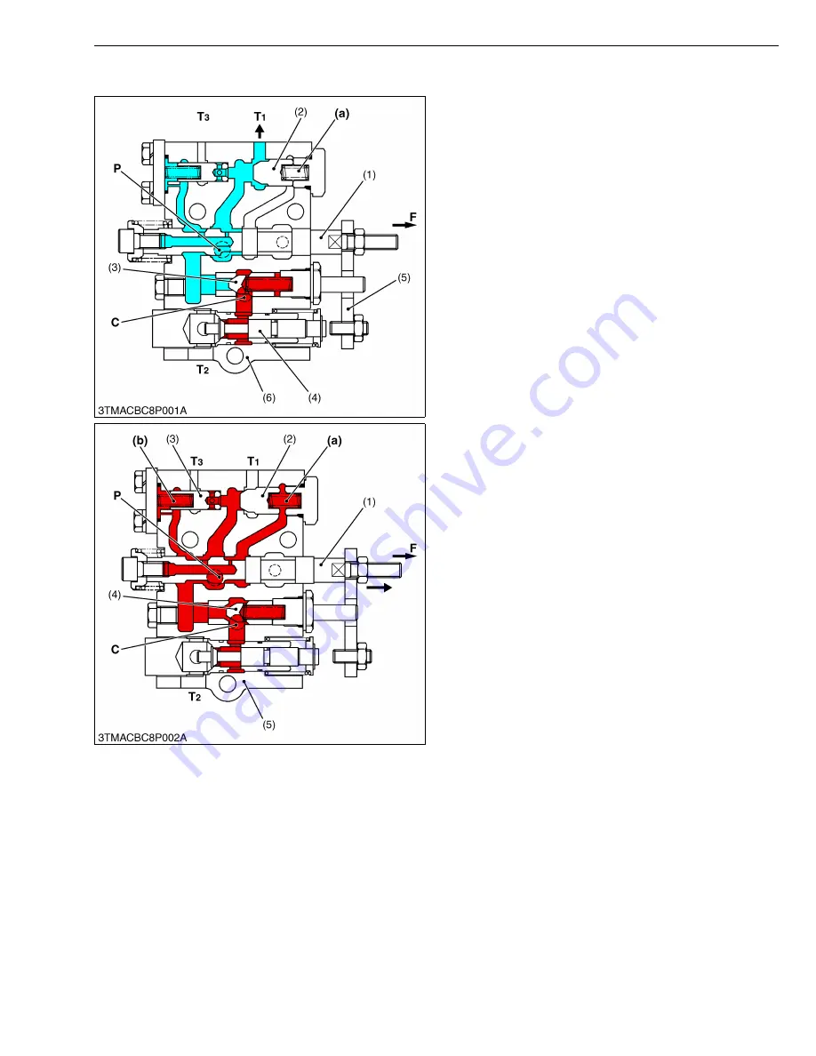
Neutral Position
Pressurized oil flows at the P port, pushes open
unload poppet (2) and returns to the transmission case
from T
1
port.
The oil in the A chamber (a) behind the unload poppet
(2) returns to the transmission case through the
clearance between spool (1) and control valve body (6).
The oil in the hydraulic cylinder does not flow out
because the circuit is cut off by the actions of poppet 1
(3) and poppet 2 (4).
W10155310
■
Lifting Position
When the control lever is moved to UP position, spool
(1) moves to arrow-mark direction. The oil entered P port
flows into the A chamber (a), B chamber (b) and closes
unload poppet (2) and poppet 3 (3).
The pressure in the circuit slowly rises, pushing open
poppet 1 (4), and the hydraulic oil flows into the hydraulic
cylinder from the C port, lifting the implement.
W10163440
(1) Spool
(2) Unload Poppet
(3) Poppet 1
(4) Poppet 2
(5) Plate
(6) Position Control Valve Body
(a) A Chamber
C : C (Cylinder) Port
P : P (Pump) Port (To Hydraulic
Pump)
T
1
: T
1
Port
(To Transmission Case)
T
2
: T
2
Port
(To Transmission Case)
T
3
: T
3
Port
(To Transmission Case)
F : Tractor Front Side
(1) Spool
(2) Unload Poppet
(3) Poppet 3
(4) Poppet 1
(5) Position Control Valve Body
(a) A Chamber
(b) B Chamber
C : C (Cylinder) Port (To
Hydraulic Pump)
P : P (Pump) Port
T
1
: T
1
Port
(To Transmission Case)
T
2
: T
2
Port
(To Transmission Case)
T
3
: T
3
Port
(To Transmission Case)
F : Tractor Front Side
Summary of Contents for MX5100
Page 2: ......
Page 8: ...6 MX5100 WSM SAFETY INSTRUCTIONS...
Page 9: ...7 MX5100 WSM SAFETY INSTRUCTIONS...
Page 12: ...10 MX5100 WSM DIMENSIONS DIMENSIONS...
Page 13: ...11 MX5100 WSM DIMENSIONS...
Page 14: ...12 MX5100 WSM DIMENSIONS...
Page 15: ...G GENERAL...
Page 16: ......
Page 18: ......
Page 87: ...1 ENGINE...
Page 88: ......
Page 90: ......
Page 92: ......
Page 166: ...1 S74 MX5100 WSM ENGINE...
Page 167: ...2 CLUTCH...
Page 168: ......
Page 170: ......
Page 174: ...2 M4 MX5100 WSM CLUTCH...
Page 176: ......
Page 205: ...3 TRANSMISSION...
Page 206: ......
Page 208: ......
Page 209: ...3 M1 MX5100 WSM TRANSMISSION 1 STRUCTURE 1 2WD...
Page 210: ...3 M2 MX5100 WSM TRANSMISSION 2 4WD...
Page 218: ......
Page 265: ...4 REAR AXLE...
Page 266: ......
Page 267: ...CONTENTS MECHANISM 1 STRUCTURE 4 M1...
Page 268: ......
Page 270: ...4 M2 MX5100 WSM REAR AXLE...
Page 272: ......
Page 278: ...4 S6 MX5100 WSM REAR AXLE...
Page 279: ...5 BRAKES...
Page 280: ......
Page 281: ...CONTENTS MECHANISM 1 STRUCTURE 5 M1...
Page 282: ......
Page 286: ......
Page 296: ...5 S10 MX5100 WSM BRAKES...
Page 297: ...6 FRONT AXLE...
Page 298: ......
Page 300: ......
Page 306: ......
Page 327: ...7 STEERING...
Page 328: ......
Page 330: ......
Page 334: ...7 M4 MX5100 WSM STEERING...
Page 336: ......
Page 355: ...8 HYDRAULIC SYSTEM...
Page 356: ......
Page 358: ......
Page 374: ......
Page 402: ...8 S28 MX5100 WSM HYDRAULIC SYSTEM...
Page 403: ...9 ELECTRICAL SYSTEM...
Page 404: ......
Page 406: ......
Page 407: ...9 M1 MX5100 WSM ELECTRICAL SYSTEM 1 WIRING DIAGRAM...
Page 420: ......
Page 454: ...9 S34 MX5100 WSM ELECTRICAL SYSTEM...


