8-S22
MX5100, WSM
HYDRAULIC SYSTEM
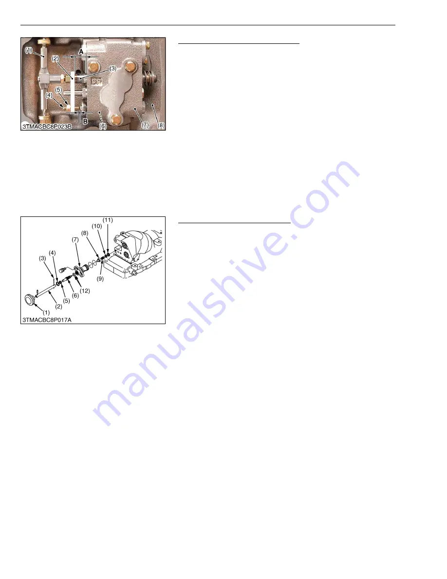
Assembling Position Control Valve
1. Install the position control valve (7) to the hydraulic cylinder (8).
2. Install the position control linkage including the position control
lever, the control arm, the spool drive lever (1), the feedback
lever shaft and the feedback rod.
3. Set the plate (1) parallel to the position control valve (7) by
moving the position control lever.
4. Set the dimension (A) between the plate 1 (2) and the control
valve to 16.0 to 16.3 mm (0.63 to 0.64 in.).
5. Turn and adjust the set screw (4) so that the clearance (B)
between the set screw (4) and the poppet 2 (6) is 0.1 to 0.2 mm
(0.0039 to 0.079 in.).
W1032363
Lowering Speed Adjusting valve
1. Remove the lowering speed adjusting valve assembly from
hydraulic cylinder block.
2. Remove the internal snap ring (4), and remove the hydraulic
adjusting shaft (6).
3. Remove the internal snap ring (11), and draw out the spring (9)
and adjusting collar (8).
(When reassembling)
• Install the hydraulic adjusting shaft (6) to valve body (7), noting
two O-rings (12).
W1026106
(1) Spool Drive Lever
(2) Plate 1
(3) Spool
(4) Set Screw
(5) Nut
(6) Poppet 2
(7) Position Control Valve
(8) Hydraulic Cylinder
A : Dimension between the plate 1
and the control valve
B : Clearance between the set screw
and the poppet 2
(1) Grip
(2) Extension Shaft
(3) Split Pin
(4) Internal Snap Ring
(5) Washer
(6) Hydraulic Adjusting Shaft
(7) Valve Body
(8) Adjusting Collar
(9) Spring
(10) Washer
(11) Internal Snap Ring
(12) O-ring
Summary of Contents for MX5100
Page 2: ......
Page 8: ...6 MX5100 WSM SAFETY INSTRUCTIONS...
Page 9: ...7 MX5100 WSM SAFETY INSTRUCTIONS...
Page 12: ...10 MX5100 WSM DIMENSIONS DIMENSIONS...
Page 13: ...11 MX5100 WSM DIMENSIONS...
Page 14: ...12 MX5100 WSM DIMENSIONS...
Page 15: ...G GENERAL...
Page 16: ......
Page 18: ......
Page 87: ...1 ENGINE...
Page 88: ......
Page 90: ......
Page 92: ......
Page 166: ...1 S74 MX5100 WSM ENGINE...
Page 167: ...2 CLUTCH...
Page 168: ......
Page 170: ......
Page 174: ...2 M4 MX5100 WSM CLUTCH...
Page 176: ......
Page 205: ...3 TRANSMISSION...
Page 206: ......
Page 208: ......
Page 209: ...3 M1 MX5100 WSM TRANSMISSION 1 STRUCTURE 1 2WD...
Page 210: ...3 M2 MX5100 WSM TRANSMISSION 2 4WD...
Page 218: ......
Page 265: ...4 REAR AXLE...
Page 266: ......
Page 267: ...CONTENTS MECHANISM 1 STRUCTURE 4 M1...
Page 268: ......
Page 270: ...4 M2 MX5100 WSM REAR AXLE...
Page 272: ......
Page 278: ...4 S6 MX5100 WSM REAR AXLE...
Page 279: ...5 BRAKES...
Page 280: ......
Page 281: ...CONTENTS MECHANISM 1 STRUCTURE 5 M1...
Page 282: ......
Page 286: ......
Page 296: ...5 S10 MX5100 WSM BRAKES...
Page 297: ...6 FRONT AXLE...
Page 298: ......
Page 300: ......
Page 306: ......
Page 327: ...7 STEERING...
Page 328: ......
Page 330: ......
Page 334: ...7 M4 MX5100 WSM STEERING...
Page 336: ......
Page 355: ...8 HYDRAULIC SYSTEM...
Page 356: ......
Page 358: ......
Page 374: ......
Page 402: ...8 S28 MX5100 WSM HYDRAULIC SYSTEM...
Page 403: ...9 ELECTRICAL SYSTEM...
Page 404: ......
Page 406: ......
Page 407: ...9 M1 MX5100 WSM ELECTRICAL SYSTEM 1 WIRING DIAGRAM...
Page 420: ......
Page 454: ...9 S34 MX5100 WSM ELECTRICAL SYSTEM...


