9
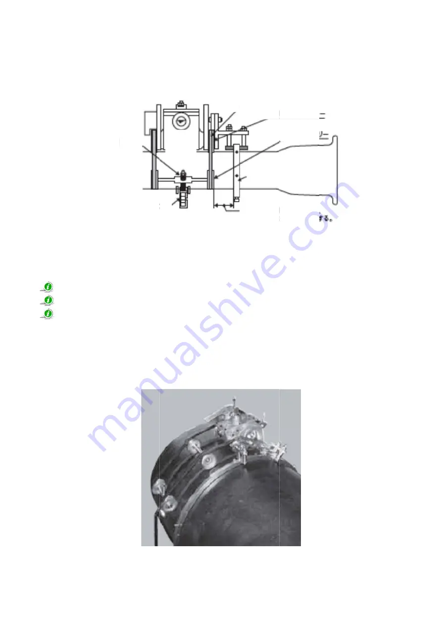
E) Adjustment of the Drive Shaft Pulley, Driven Shaft Pulley, V-Belts and the Roller Chain shall be
parallel to the Guide Ring. (Fig.7)
Fig.7
V-Belt
Drive Shaft Pulley
Driven Shaft Pulley
Adjusting Long Screw
Guide Ring
Roller Chain
Adjust this distance
around
.
same all the way
F) Turn the Crank Handle and press the center of the V-Belts to check the tension with your finger
once in a while. Tension is appropriate when the V-Belts are not elastic of finger pressing.
Tip! For any pipe larger than 20”, Double pulley assembly is necessary. (Pict.10)
Tip! Single pulley assembly makes the V-Belts slip on the pipe
Tip! When making double pulley assembly, install the C-45 V-Belts on the inner side of the First
Driven Shaft (w/ Double Driven Shaft Pulley) at first. Connect the First Driven Shaft and
the Drive Shaft Pulley. After this work is finished, install other sides of the C-45 V-Belts on
the Second Driven Shaft (w/ Single Driven Shaft Pulley).
Pict.10
Main
Body


