The flywheel periphery is inscribed with the marks
showing fuel injection timing angle lines and top dead
center mark TC. The flywheel (2) mounted on the rear
of the crankshaft (1) is a stabilizer for the whole engine.
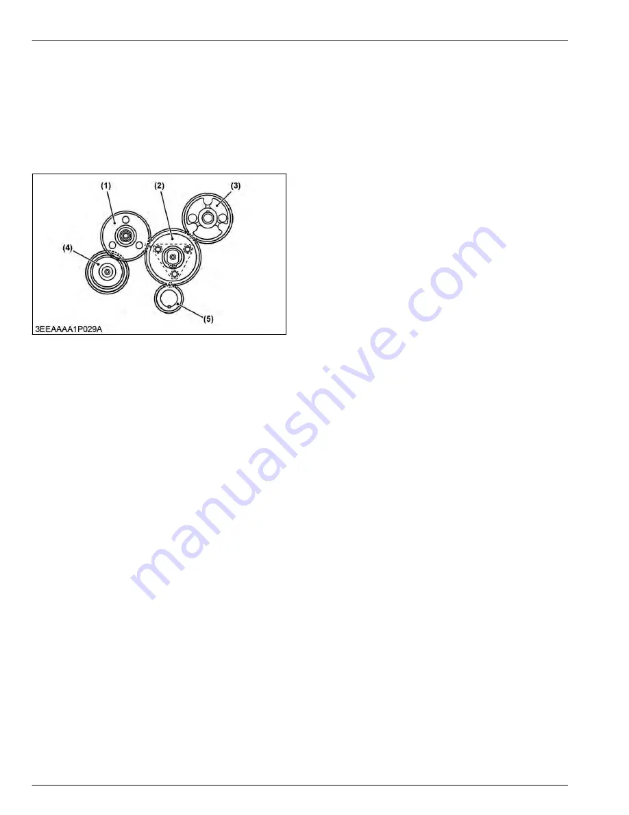
1.11 Function of timing gears
The timing gears correctly control fuel injection to the
cylinders and valve timing.
(1) Injection pump gear
(2) Idle gear
(3) Cam gear
(4) Governor gear
(5) Crank gear
The timing gears transmit torque from the crankshaft to
the oil pump and injection pump and, at the same time,
correctly control fuel injection to the cylinders and valve
timing. Each gear has a mating mark inscribed on it for
correct and easy assembly and is spherical with teeth
set obliquely to the axis of rotation to rotate smoothly
and reduce noise. The crankshaft is the hub around
which other parts of the engine can be timed and
driven. This is done by the meshing of gears as shown
in the figure.
3. ENGINE
MECHANISM
1. Engine body
3-4
BX1880,BX2380,BX2680,RCK60B-23BX,RCK54-23BX,RCK48-18BX,RCK60D-26BX,RCK54D-26BX
KiSC issued 03, 2019 A
Summary of Contents for ,RCK60B-23BX
Page 19: ...1 INFORMATION KiSC issued 03 2019 A ...
Page 42: ...2 GENERAL KiSC issued 03 2019 A ...
Page 111: ...3 ENGINE KiSC issued 03 2019 A ...
Page 190: ...4 TRANSAXLE KiSC issued 03 2019 A ...
Page 255: ...5 FRONT AXLE KiSC issued 03 2019 A ...
Page 274: ...6 STEERING KiSC issued 03 2019 A ...
Page 291: ...7 HYDRAULIC SYSTEM KiSC issued 03 2019 A ...
Page 344: ...8 ELECTRICAL SYSTEM KiSC issued 03 2019 A ...
Page 399: ...9 MOWER KiSC issued 03 2019 A ...


