• Apply clean engine oil on the bearings.
• Install the main bearing case assemblies in the
original positions.
Since diameters of main bearing cases vary, install
them in order of markings (b) (
[A]
,
[B]
,
[C]
) from
the gear case side.
• Match the alignment numbers (a) on the main
bearing case assembly 1.
• When installing the main bearing case 1 and 2, face
the mark
[FLYWHEEL]
to the flywheel.
• Install the thrust bearing (3) with its oil groove
facing outward.
• Make sure that the main bearing case moves
smoothly after tightening the main bearing case
screw 1 to the specified torque.
BX1880 and BX2380
Tightening tor-
que
Main bearing case
screw 1
13 to 15 N
⋅
m
1.4 to 1.5 kgf
⋅
m
9.6 to 11 lbf
⋅
ft
BX2680
Tightening tor-
que
Main bearing case
screw 1
30 to 34 N
⋅
m
3.1 to 3.4 kgf
⋅
m
23 to 25 lbf
⋅
ft
6. Servicing
6.1 Cylinder head and valve
6.1.1 Checking top clearance
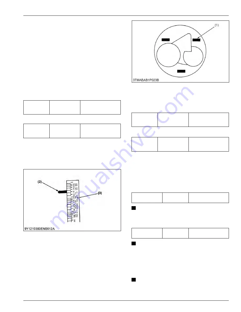
(2) Crushed plastigauge
(3) Scale
1. Remove the cylinder head.
2. With the piston at T.D.C., use grease to affix three
or four plastigauges (1) of a diameter 1.5 mm
(0.059 in.) × 5.0 to 7.0 mm (0.20 to 0.27 in.) long to
the crown of the piston; keep the gauges away from
the intake valve and combustion chamber fittings.
(1) Plastigauge
3. Take the piston to an intermediate position, install
the cylinder head and tighten the head bolts to the
specified torque.
BX1880 and BX2380
Tightening tor-
que
Cylinder head
screw
38 to 42 N
⋅
m
3.9 to 4.2 kgf
⋅
m
28 to 30 lbf
⋅
ft
BX2680
Tightening tor-
que
Cylinder head
screw
64 to 68 N
⋅
m
6.6 to 6.9 kgf
⋅
m
48 to 50 lbf
⋅
ft
4. Turn the crankshaft so the piston goes through
T.D.C.
5. Remove the cylinder head and compare the width
of the crushed plastigauges (2) with the scale.
6. If they are out of specification, check the oil
clearance of the crank pin, journals and piston pins.
BX1880 and BX2380
Top clearance
Factory specifi-
cation
0.55 to 0.70 mm
0.022 to 0.028 in.
NOTE
•
Top clearance = Width of the crushed plastigauge (2).
BX2680
Top clearance
Factory specifi-
cation
0.55 to 0.75 mm
0.022 to 0.030 in.
NOTE
•
Top clearance = Width of the crushed plastigauge (2).
6.1.2 Checking cylinder head surface
flatness
IMPORTANT
• Do not place the straightedge on the
combustion chamber.
SERVICING
6. Servicing
3. ENGINE
BX1880,BX2380,BX2680,RCK60B-23BX,RCK54-23BX,RCK48-18BX,RCK60D-26BX,RCK54D-26BX
3-55
KiSC issued 03, 2019 A
Summary of Contents for ,RCK60B-23BX
Page 19: ...1 INFORMATION KiSC issued 03 2019 A ...
Page 42: ...2 GENERAL KiSC issued 03 2019 A ...
Page 111: ...3 ENGINE KiSC issued 03 2019 A ...
Page 190: ...4 TRANSAXLE KiSC issued 03 2019 A ...
Page 255: ...5 FRONT AXLE KiSC issued 03 2019 A ...
Page 274: ...6 STEERING KiSC issued 03 2019 A ...
Page 291: ...7 HYDRAULIC SYSTEM KiSC issued 03 2019 A ...
Page 344: ...8 ELECTRICAL SYSTEM KiSC issued 03 2019 A ...
Page 399: ...9 MOWER KiSC issued 03 2019 A ...


