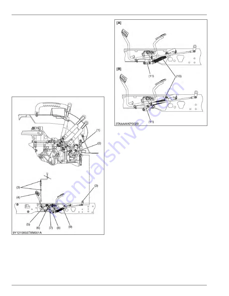
2.1.3 Structure of HST control linkage
The speed control pedal (4) and the trunnion arm are
linked with the HST pedal link (8) and the speed
change rod (9). As the front of the pedal is depressed,
the swashplate connected to the trunnion arm (2)
rotates and forward travelling speed increases.
Depressing the rear end increases reverse speed.
The trunnion arm (2) is returned to neutral position by
the neutral arm and the tension of neutral spring. At the
same time, the swashplate is returned to neutral, when
the pedal is released. The damper (10) connected to
the HST pedal link (8) restricts the movement of the
linkage to prevent abrupt operation or reversing.
Moreover, the feeling of the dynamic braking can be
adjusted by changing the arm (11) position of damper
(10).
(1) Neutral spring
(2) Trunnion arm
(3) Cruise rod
(4) Speed control pedal
(5) Cruise arm
(6) Cruise lock
(7) Cruise lock
(8) HST pedal link
(9) Speed change rod
(10) Damper
(11) Arm
(Reference)
[A]
Force of the damper is large.
[B]
Force of the damper is small.
4. TRANSAXLE
MECHANISM
2. Traveling system
4-8
BX1880,BX2380,BX2680,RCK60B-23BX,RCK54-23BX,RCK48-18BX,RCK60D-26BX,RCK54D-26BX
KiSC issued 03, 2019 A
Summary of Contents for ,RCK60B-23BX
Page 19: ...1 INFORMATION KiSC issued 03 2019 A ...
Page 42: ...2 GENERAL KiSC issued 03 2019 A ...
Page 111: ...3 ENGINE KiSC issued 03 2019 A ...
Page 190: ...4 TRANSAXLE KiSC issued 03 2019 A ...
Page 255: ...5 FRONT AXLE KiSC issued 03 2019 A ...
Page 274: ...6 STEERING KiSC issued 03 2019 A ...
Page 291: ...7 HYDRAULIC SYSTEM KiSC issued 03 2019 A ...
Page 344: ...8 ELECTRICAL SYSTEM KiSC issued 03 2019 A ...
Page 399: ...9 MOWER KiSC issued 03 2019 A ...


