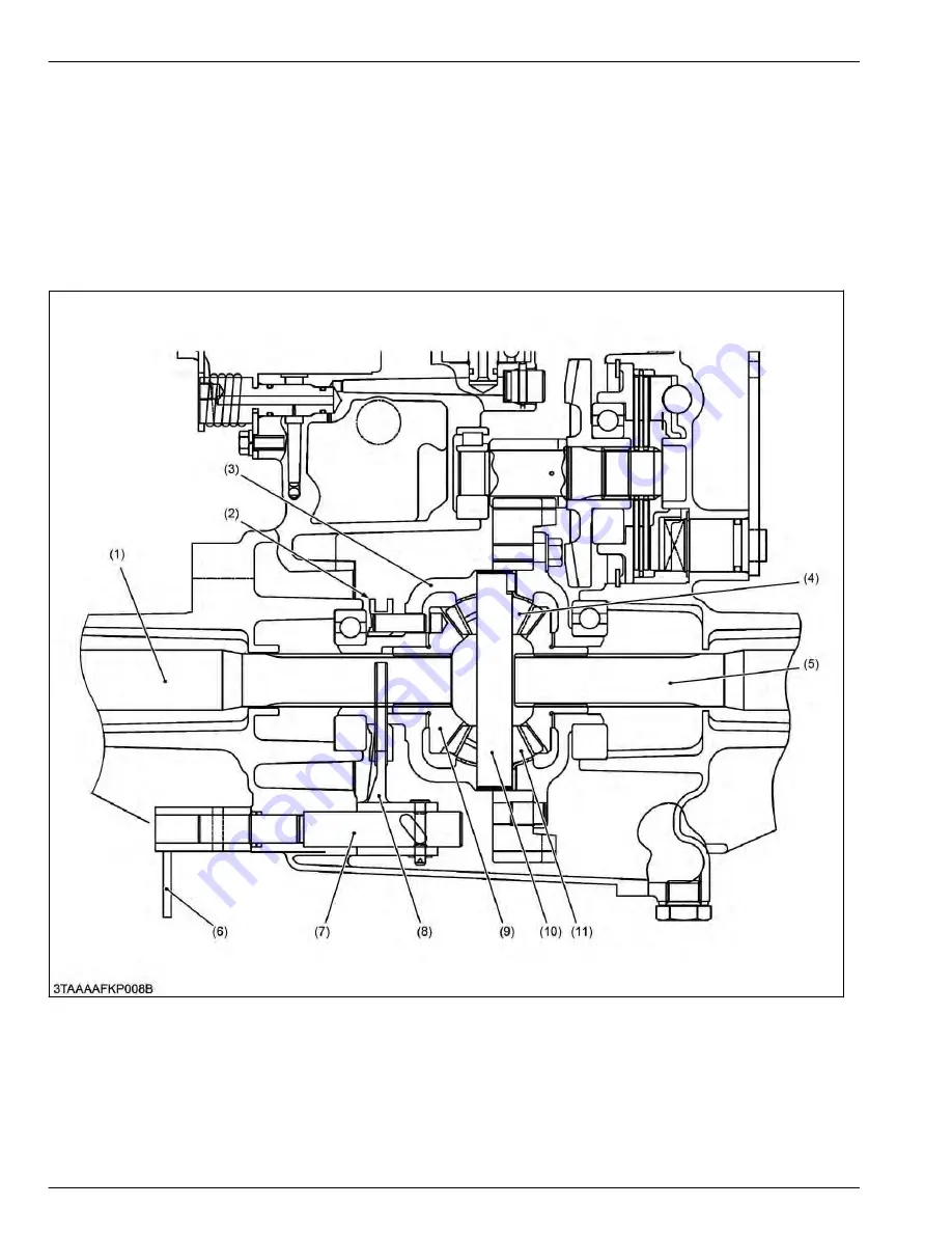
2.4.2 Structure of differential lock
When resistance to the right and left tires are greatly different due to ground conditions or type of work, the tire with
less resistance slips and prevents the tractor from moving ahead. To compensate for this drawback, the differential
lock restricts the differential action and causes both rear axles to rotate as a unit.
When the differential lock pedal is stepped on, it causes the differential lock arm (6) and differential lock shaft (7) to
rotate, which will move the differential lock shift fork (8) and the differential lock shifter (2) toward the differential side
gear (9). The pins on the differential lock shifter (2) go into the holes in the differential case (3) to cause the differential
case (3), differential lock shifter (2) and differential side gear (9) to rotate as a unit.
Therefore, differential pinions (4), (11) are unable to rotate around differential pinion shaft (10) and identical
revolutions are transmitted to the right and left rear axle (1), (5).
(1) Rear axle
(2) Differential lock shifter
(3) Differential case
(4) Differential pinion
(5) Rear axle
(6) Differential lock arm
(7) Differential lock shaft
(8) Differential lock shift fork
(9) Differential side gear
(10) Differential pinion shaft
(11) Differential pinion
4. TRANSAXLE
MECHANISM
2. Traveling system
4-16
BX1880,BX2380,BX2680,RCK60B-23BX,RCK54-23BX,RCK48-18BX,RCK60D-26BX,RCK54D-26BX
KiSC issued 03, 2019 A
Summary of Contents for ,RCK60B-23BX
Page 19: ...1 INFORMATION KiSC issued 03 2019 A ...
Page 42: ...2 GENERAL KiSC issued 03 2019 A ...
Page 111: ...3 ENGINE KiSC issued 03 2019 A ...
Page 190: ...4 TRANSAXLE KiSC issued 03 2019 A ...
Page 255: ...5 FRONT AXLE KiSC issued 03 2019 A ...
Page 274: ...6 STEERING KiSC issued 03 2019 A ...
Page 291: ...7 HYDRAULIC SYSTEM KiSC issued 03 2019 A ...
Page 344: ...8 ELECTRICAL SYSTEM KiSC issued 03 2019 A ...
Page 399: ...9 MOWER KiSC issued 03 2019 A ...


