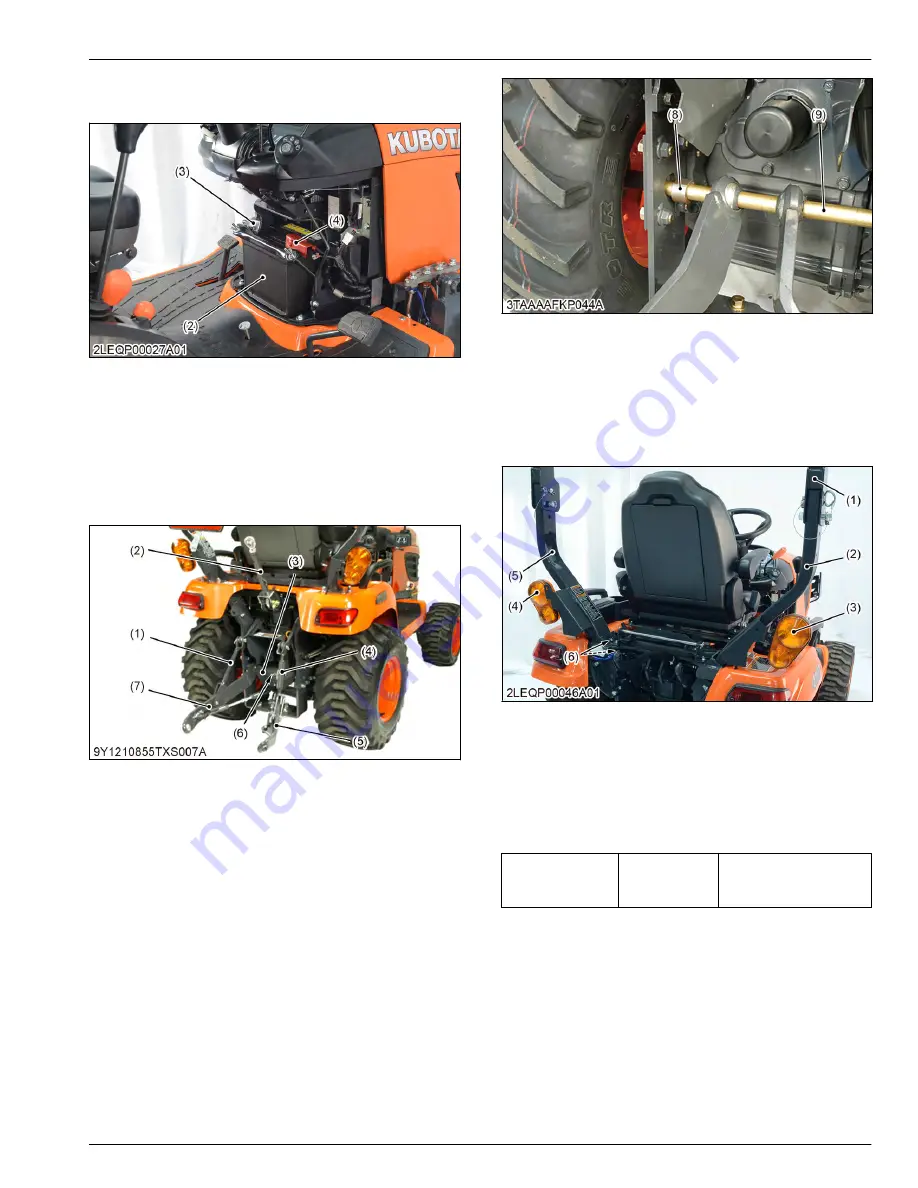
3. Disconnect the positive cable (4) from the battery
(2) and remove the battery.
(2) Battery
(3) Negative cable
(4) Positive cable
5.1.3 Removing lift rod and lower link
1. Remove the top link (2).
2. Remove the stopper pin (6) and remove the check
chain plate (3).
(1) Lift rod L.H.
(2) Top link
(3) Check chain plate
(4) Lift rod R.H.
(5) Lower link R.H.
(6) Stopper pin
(7) Lower link L.H.
3. Move the bushes (8) to inside.
4. Move the shaft (9) to right side and remove the
lower link as a unit.
(8) Bush
(9) Shaft
5.1.4 Removing ROPS
1. Disconnect the R.H and L.H. hazard lamp/turn
signals (3), (4) from the wire harness.
2. Remove the upper ROPS (1).
(1) Upper ROPS
(2) R.H. lower ROPS
(3) R.H. hazard lamp/turn signal
(4) L.H. hazard lamp/turn signal
(5) L.H. lower ROPS
(6) Bolt
3. Remove the ROPS mounting bolts (6).
4. Remove the R.H. and L.H. lower ROPS (2), (5).
(When reassembling)
Tightening torque
ROPS mount-
ing bolt
48.0 to 55.9 N
⋅
m
4.90 to 5.70 kgf
⋅
m
35.5 to 41.2 lbf
⋅
ft
5.1.5 Removing seat
1. Disconnect the seat switch connectors.
SERVICING
5. Disassembling and assembling
4. TRANSAXLE
BX1880,BX2380,BX2680,RCK60B-23BX,RCK54-23BX,RCK48-18BX,RCK60D-26BX,RCK54D-26BX
4-37
KiSC issued 03, 2019 A
Summary of Contents for ,RCK60B-23BX
Page 19: ...1 INFORMATION KiSC issued 03 2019 A ...
Page 42: ...2 GENERAL KiSC issued 03 2019 A ...
Page 111: ...3 ENGINE KiSC issued 03 2019 A ...
Page 190: ...4 TRANSAXLE KiSC issued 03 2019 A ...
Page 255: ...5 FRONT AXLE KiSC issued 03 2019 A ...
Page 274: ...6 STEERING KiSC issued 03 2019 A ...
Page 291: ...7 HYDRAULIC SYSTEM KiSC issued 03 2019 A ...
Page 344: ...8 ELECTRICAL SYSTEM KiSC issued 03 2019 A ...
Page 399: ...9 MOWER KiSC issued 03 2019 A ...


