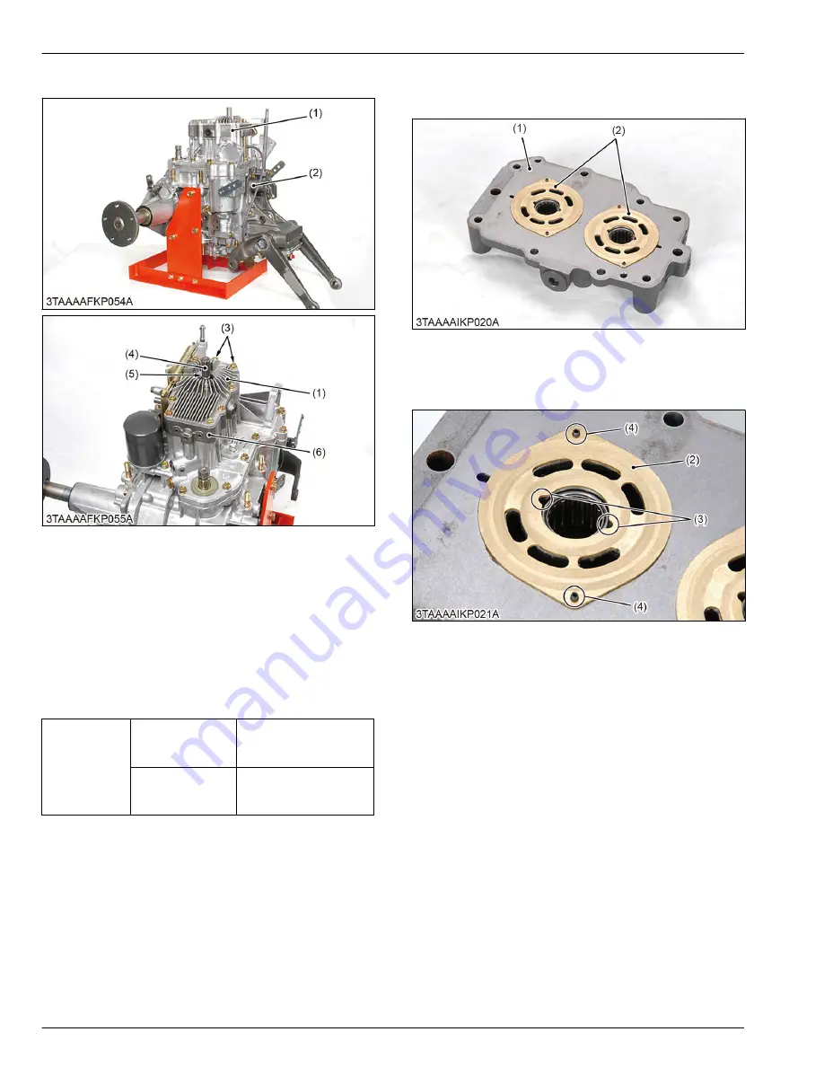
5.2.3 Removing oil cooler cover
(1) HST front cover
(2) Transaxle assembly
(3) Bolt
(4) Internal circlip
(5) Oil seal
(6) Center section
1. Remove the HST front cover (1) not to damage the
oil seal (5).
2. Remove the center section (6).
(When reassembling)
• Do not damage the oil seal (5).
• Tighten the HST mounting bolts and the nut to the
factory specifications.
Tightening tor-
que
Oil cooler cover
mounting bolt (M8)
18 to 20 N
⋅
m
1.8 to 2.1 kgf
⋅
m
13 to 15 lbf
⋅
ft
Oil cooler cover
mounting nut (M8)
18 to 20 N
⋅
m
1.8 to 2.1 kgf
⋅
m
13 to 15 lbf
⋅
ft
5.2.4 Removing center section and valve
plates
(1) Center section
(2) Valve plate
1. Remove the valve plates (2).
(When reassembling)
(2) Valve plate
(3) Groove
(4) Anchor pin
1. Check the direction of the groove (3).
2. Install the valve plates (2) to the anchor pins (4)
securely.
3. Install the groove of the valve plate (pump plate) to
the engine side.
4. TRANSAXLE
SERVICING
5. Disassembling and assembling
4-44
BX1880,BX2380,BX2680,RCK60B-23BX,RCK54-23BX,RCK48-18BX,RCK60D-26BX,RCK54D-26BX
KiSC issued 03, 2019 A
Summary of Contents for ,RCK60B-23BX
Page 19: ...1 INFORMATION KiSC issued 03 2019 A ...
Page 42: ...2 GENERAL KiSC issued 03 2019 A ...
Page 111: ...3 ENGINE KiSC issued 03 2019 A ...
Page 190: ...4 TRANSAXLE KiSC issued 03 2019 A ...
Page 255: ...5 FRONT AXLE KiSC issued 03 2019 A ...
Page 274: ...6 STEERING KiSC issued 03 2019 A ...
Page 291: ...7 HYDRAULIC SYSTEM KiSC issued 03 2019 A ...
Page 344: ...8 ELECTRICAL SYSTEM KiSC issued 03 2019 A ...
Page 399: ...9 MOWER KiSC issued 03 2019 A ...


