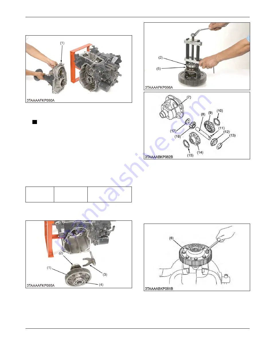
2. Remove the rear axle case (R.H.) (1) as an
assembly from the transaxle case.
(1) Rear axle case (R.H.)
3. Remove the 37T spiral bevel gear (2).
NOTE
• Since the adjusting shims are installed
behind the 37T spiral bevel gear, check the
shims.
4. Remove the 10T final gear shaft (3).
5. Remove the 66T final gear with the differential lock
shift fork.
(When reassembling)
• Apply liquid gasket (Three Bond 1208D or
equivalent) to the joint surface of transaxle case to
the rear axle case (R.H.).
Tightening tor-
que
Rear axle case
(R.H.) mounting
bolt (M8)
18 to 20 N
⋅
m
1.8 to 2.1 kgf
⋅
m
13 to 15 lbf
⋅
ft
5.4.6 Removing 66T final gear
(1) 66T final gear
(2) Bearing
(3) Differential lock shift fork
(4) Bearing
(5) Differential lock shifter
(7) Differential case
(8) Differential pinion shaft
(9) Differential side gear
(10) Differential side gear washer
(11) Key
(12) Differential pinion
(13) Differential pinion washer
(14) Differential side gear
(15) Differential side gear washer
(16) Differential pinion
(17) Differential pinion washer
1. Remove the bearing (2) with a puller.
2. Remove the bearing (4) with a puller.
3. Remove the differential lock shifter (5) and 66T final
gear (6).
(6) 66T final gear
4. Put parting marks on the differential pinions (12),
(16) and the differential side gears (9), (14).
5. Tap out the differential pinion shaft (8).
SERVICING
5. Disassembling and assembling
4. TRANSAXLE
BX1880,BX2380,BX2680,RCK60B-23BX,RCK54-23BX,RCK48-18BX,RCK60D-26BX,RCK54D-26BX
4-53
KiSC issued 03, 2019 A
Summary of Contents for ,RCK60B-23BX
Page 19: ...1 INFORMATION KiSC issued 03 2019 A ...
Page 42: ...2 GENERAL KiSC issued 03 2019 A ...
Page 111: ...3 ENGINE KiSC issued 03 2019 A ...
Page 190: ...4 TRANSAXLE KiSC issued 03 2019 A ...
Page 255: ...5 FRONT AXLE KiSC issued 03 2019 A ...
Page 274: ...6 STEERING KiSC issued 03 2019 A ...
Page 291: ...7 HYDRAULIC SYSTEM KiSC issued 03 2019 A ...
Page 344: ...8 ELECTRICAL SYSTEM KiSC issued 03 2019 A ...
Page 399: ...9 MOWER KiSC issued 03 2019 A ...


