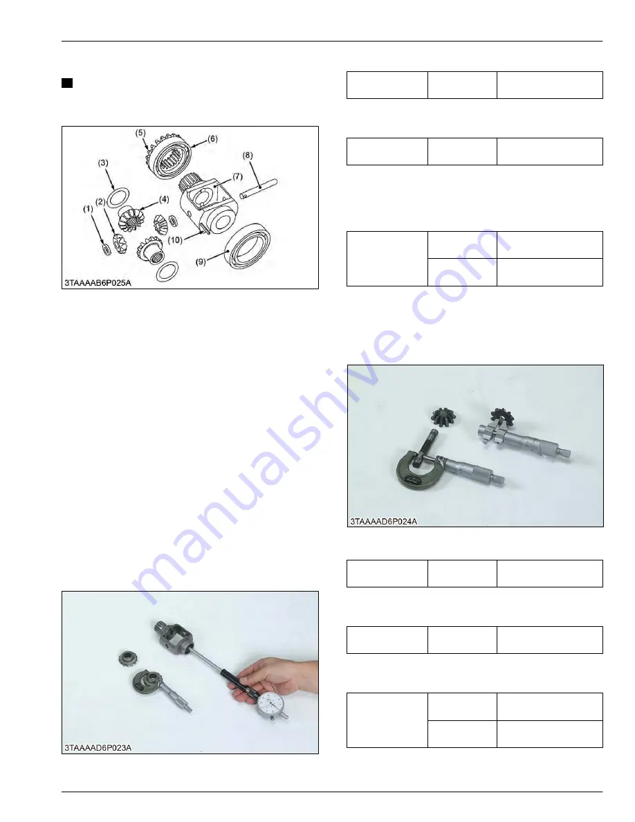
5.2.7 Removing differential gear
NOTE
• Arrange the parts to know their original
position.
(1) Shim
(2) Differential pinion
(3) Shim
(4) Differential side gear
(5) Bevel gear
(6) Bearing
(7) Differential gear case
(8) Differential pinion shaft
(9) Ball bearing
(10) Spring pin
1. Remove the bevel gear (5) with bearing (6) and ball
bearing (9) by puller.
2. Remove the spring pin (10).
3. Remove the differential pinion shaft (8).
4. Remove the differential pinions (2), differential side
gears (4) and shims (1), (3).
(When reassembling)
• Apply molybdenum disulfide (Three Bond 1901 or
equivalent) to the inner circumferential surface of
the differential side gears, differential pinions and
shims.
6. Servicing
6.1 Checking clearance between
differential case and differential side
gear
1. Measure the differential side gear boss O.D.
Differential side
gear O.D.
Factory specifi-
cation
25.939 to 25.960 mm
1.0213 to 1.0220 in.
2. Measure the differential case bore I.D., and
calculate the clearance.
Differential case
bore I.D.
Factory specifi-
cation
26.000 to 26.021 mm
1.0237 to 1.0244 in.
3. Measure the differential case cover bore I.D., and
calculate the clearance.
4. If the clearance exceeds the allowable limit, replace
damaged parts.
Clearance be-
tween differential
case and differen-
tial side gear
Factory specifi-
cation
0.040 to 0.082 mm
0.0016 to 0.0032 in.
Allowable limit
0.17 mm
0.0067 in.
6.2 Checking clearance between
differential pinion shaft and
differential pinion
1. Measure the differential pinion shaft O.D.
Differential pinion
shaft O.D.
Factory specifi-
cation
9.960 to 9.975 mm
0.3922 to 0.3927 in.
2. Measure the differential pinion I.D., and calculate
the clearance.
Differential pinion
I.D.
Factory specifi-
cation
10.000 to 10.015 mm
0.39370 to 0.39429 in.
3. If the clearance exceeds the allowable limit, replace
damaged parts.
Clearance be-
tween differential
pinion shaft and
differential pinion
Factory specifi-
cation
0.025 to 0.055 mm
0.00099 to 0.0021 in.
Allowable limit
0.25 mm
0.0098 in.
SERVICING
5. Disassembling and assembling
5. FRONT AXLE
BX1880,BX2380,BX2680,RCK60B-23BX,RCK54-23BX,RCK48-18BX,RCK60D-26BX,RCK54D-26BX
5-15
KiSC issued 03, 2019 A
Summary of Contents for ,RCK60B-23BX
Page 19: ...1 INFORMATION KiSC issued 03 2019 A ...
Page 42: ...2 GENERAL KiSC issued 03 2019 A ...
Page 111: ...3 ENGINE KiSC issued 03 2019 A ...
Page 190: ...4 TRANSAXLE KiSC issued 03 2019 A ...
Page 255: ...5 FRONT AXLE KiSC issued 03 2019 A ...
Page 274: ...6 STEERING KiSC issued 03 2019 A ...
Page 291: ...7 HYDRAULIC SYSTEM KiSC issued 03 2019 A ...
Page 344: ...8 ELECTRICAL SYSTEM KiSC issued 03 2019 A ...
Page 399: ...9 MOWER KiSC issued 03 2019 A ...


