2. Hydraulic circuit of steering
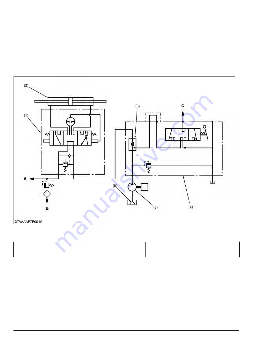
The steering circuit consists of a steering controller (1), steering cylinder (2), flow priority valve (3), hydraulic control
valve assembly (4), hydraulic pump (5), and oil strainer (6).
Oil is supplied from the oil strainer by the hydraulic pump to the flow priority valve.
The flow priority valve then divides the oil into two directions. The priority direction is to control the oil flow to the
power steering at a fixed control rate. The secondary direction is excessive flow to the control valve of the implement
lift circuit.
The oil that is supplied to the steering system gets transferred to the steering controller. When the steering wheel is
turned, the steering controller then transfers oil to the steering cylinder.
(1) Steering controller
(2) Steering cylinder
(3) Flow priority valve
(4) Hydraulic control valve as-
sembly
(5) Hydraulic pump
(6) Oil strainer
A:
To PTO clutch valve
B:
To HST
C:
To hydraulic cylinder
Oil flow rate
Flow priority valve
8.0 L/min.
2.1 U.S.gals/min.
1.8 Imp.gals/min.
6. STEERING
MECHANISM
2. Hydraulic circuit of steering
6-2
BX1880,BX2380,BX2680,RCK60B-23BX,RCK54-23BX,RCK48-18BX,RCK60D-26BX,RCK54D-26BX
KiSC issued 03, 2019 A
Summary of Contents for ,RCK60B-23BX
Page 19: ...1 INFORMATION KiSC issued 03 2019 A ...
Page 42: ...2 GENERAL KiSC issued 03 2019 A ...
Page 111: ...3 ENGINE KiSC issued 03 2019 A ...
Page 190: ...4 TRANSAXLE KiSC issued 03 2019 A ...
Page 255: ...5 FRONT AXLE KiSC issued 03 2019 A ...
Page 274: ...6 STEERING KiSC issued 03 2019 A ...
Page 291: ...7 HYDRAULIC SYSTEM KiSC issued 03 2019 A ...
Page 344: ...8 ELECTRICAL SYSTEM KiSC issued 03 2019 A ...
Page 399: ...9 MOWER KiSC issued 03 2019 A ...


