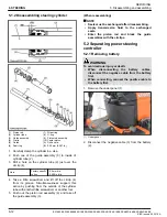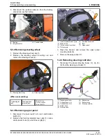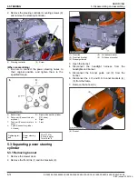
5.3.2 Removing front axle assembly
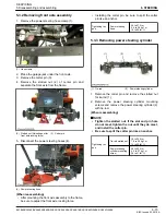
1. Remove the power steering hose clamp (1).
(1) Hose clamp
2. Place the garage jack under the front axle.
3. Remove the cotter pin (3).
4. Remove the slotted nut (2) of center pin and
separate the front axle from the frame.
(2) Slotted nut (Adjusting nut for
front axle rocking force)
(3) Cotter pin
5. Disconnect the power steering hoses (4).
(4) Power steering hose
(When reassembling)
• After mounting the front axle assembly to the frame,
be sure to adjust the front axle rocking force.
• Installing the cotter pin, be sure to split the cotter
pin like an anchor.
Tightening tor-
que
Power steering
hose
24 to 27 N
⋅
m
2.4 to 2.8 kgf
⋅
m
18 to 20 lbf
⋅
ft
5.3.3 Removing power steering cylinder
(1) Tie-rod
(2) Power steering cylinder
1. Remove the cotter pin and remove the slotted nut
for tie-rod (1).
2. Remove the power steering cylinder mounting
screws and remove the power steering cylinder (2)
with tie-rod.
(When reassembling)
NOTE
• Tighten the slotted nut. If the slot and pin hole
do not meet, tighten the nut until they do meet,
and install the cotter pin.
• Be sure to split the cotter pin like an anchor.
Tightening tor-
que
Tie-rod slotted nut
18 to 34 N
⋅
m
1.8 to 3.5 kgf
⋅
m
13 to 25 lbf
⋅
ft
Power steering
cylinder mounting
screw
48 to 55 N
⋅
m
4.9 to 5.7 kgf
⋅
m
36 to 41 lbf
⋅
ft
SERVICING
5. Disassembling and assembling
6. STEERING
BX1880,BX2380,BX2680,RCK60B-23BX,RCK54-23BX,RCK48-18BX,RCK60D-26BX,RCK54D-26BX
6-15
KiSC issued 03, 2019 A
Summary of Contents for ,RCK60B-23BX
Page 19: ...1 INFORMATION KiSC issued 03 2019 A ...
Page 42: ...2 GENERAL KiSC issued 03 2019 A ...
Page 111: ...3 ENGINE KiSC issued 03 2019 A ...
Page 190: ...4 TRANSAXLE KiSC issued 03 2019 A ...
Page 255: ...5 FRONT AXLE KiSC issued 03 2019 A ...
Page 274: ...6 STEERING KiSC issued 03 2019 A ...
Page 291: ...7 HYDRAULIC SYSTEM KiSC issued 03 2019 A ...
Page 344: ...8 ELECTRICAL SYSTEM KiSC issued 03 2019 A ...
Page 399: ...9 MOWER KiSC issued 03 2019 A ...


