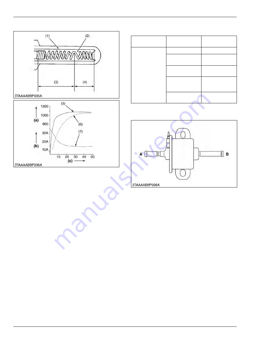
4.4 Function of glow plug
(1) Sheath tube
(2) Insulation powder
(3) Heater also functioning as a
resistor
(4) Heater
(5) Super glow plug
(6) Conventional quick-heating
type glow plug
(7) Glow plug current
(a) Glow plug temperature (
℃
)
(b) Current (A)
(c) Time (Sec.)
This plug is a two-material type QGS (Quick Glow
System) for quick temperature rise, and has self-
controlling function as well as excellent durability.
The heater (4) connected in series to the heater (3),
which also functions as the resistor, is incorporated in
the sheath tube (1) of the super glow plug.
The resistance of this heater (3) cum resistor is small
when the temperature is low, while the resistance
becomes large when the temperature rises.
Therefore, because sufficient current is flown to the
heater (4) during the initial period of energization, the
temperature rises quickly and the resistance grows with
the rise in the temperature of the resistor, the flowing
current is reduces to prevent the heater (4) from being
heated.
The ignition point is in the area of 2 to 3 mm (0.079 to
0.118 in.) from the tip of the plug in order to reduce its
projection into the combustion chamber.
4.5 Function of safety switch
The safety switch is electrically closed in normal
condition (normally closed type). The switch operates
as sensor detecting and transmitting the position of
HST pedal, PTO lever, independent PTO lever, and
seat to engine stop solenoid.
Type of switch
Safety switch
name
Number of switch
contact
Normal open type
Seat switch
1
Seat turnover
switch
1
PTO shift lever
switch
1
Independent PTO
lever switch (Rear
PTO switch)
2
HST pedal neutral
switch
2
4.6 Function of fuel pump
A:
Inlet
B:
Outlet
An electromagnetic fuel pump uses a transistor that
causes the pump to start pumping fuel when the main
switch is turned to the
ON
position. Therefore, fuel is
supplied to the fuel injection pump regardless of engine
speed. This pump is driven by the battery. It can
therefore be operated even with the engine being
stopped.
8. ELECTRICAL SYSTEM
MECHANISM
4. Starting system
8-10
BX1880,BX2380,BX2680,RCK60B-23BX,RCK54-23BX,RCK48-18BX,RCK60D-26BX,RCK54D-26BX
KiSC issued 03, 2019 A
Summary of Contents for ,RCK60B-23BX
Page 19: ...1 INFORMATION KiSC issued 03 2019 A ...
Page 42: ...2 GENERAL KiSC issued 03 2019 A ...
Page 111: ...3 ENGINE KiSC issued 03 2019 A ...
Page 190: ...4 TRANSAXLE KiSC issued 03 2019 A ...
Page 255: ...5 FRONT AXLE KiSC issued 03 2019 A ...
Page 274: ...6 STEERING KiSC issued 03 2019 A ...
Page 291: ...7 HYDRAULIC SYSTEM KiSC issued 03 2019 A ...
Page 344: ...8 ELECTRICAL SYSTEM KiSC issued 03 2019 A ...
Page 399: ...9 MOWER KiSC issued 03 2019 A ...


