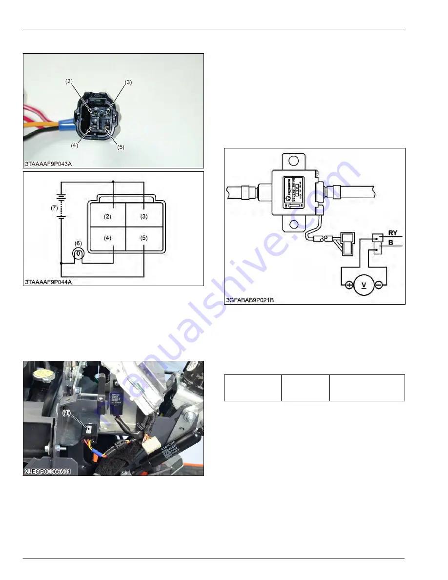
4.6.2 Checking OPC timer
(2) Orange / white terminal
(from battery)
(3) Yellow terminal (from OPC
switch)
(4) Red terminal (to key stop
solenoid)
(5) Black terminal (to frame
earth)
(6) Bulb (Load)
(7) Battery
1. Remove the OPC timer.
The OPC timer is located under the upper panel.
(1) OPC timer
2. Connect the jumper leads across the battery
terminal and the red / white terminal (2), and across
the battery positive terminal and the yellow terminal
(3).
3. Connect the jumper lead across the battery
negative terminal and the black terminal (5), and
across the battery negative terminal and the bulb
terminal.
4. Connect the jumper lead across the red terminal (4)
and the bulb terminal.
5. If the bulb lights up when disconnecting the jumper
lead from the red / white terminal (2), the OPC timer
(1) is proper.
4.7 Fuel pump
4.7.1 Checking fuel pump connector
voltage
1. Disconnect the 2P connector from the fuel pump.
2. Turn the main switch key to the
ON
position, and
measure the voltage with a voltmeter between the
connector terminals.
3. If the voltage differs from the battery voltage, the
wiring harness or main switch is damaged.
Voltage
Between con-
nector termi-
nals
Approx. battery voltage
8. ELECTRICAL SYSTEM
SERVICING
4. Checking and adjusting
8-36
BX1880,BX2380,BX2680,RCK60B-23BX,RCK54-23BX,RCK48-18BX,RCK60D-26BX,RCK54D-26BX
KiSC issued 03, 2019 A
Summary of Contents for ,RCK60B-23BX
Page 19: ...1 INFORMATION KiSC issued 03 2019 A ...
Page 42: ...2 GENERAL KiSC issued 03 2019 A ...
Page 111: ...3 ENGINE KiSC issued 03 2019 A ...
Page 190: ...4 TRANSAXLE KiSC issued 03 2019 A ...
Page 255: ...5 FRONT AXLE KiSC issued 03 2019 A ...
Page 274: ...6 STEERING KiSC issued 03 2019 A ...
Page 291: ...7 HYDRAULIC SYSTEM KiSC issued 03 2019 A ...
Page 344: ...8 ELECTRICAL SYSTEM KiSC issued 03 2019 A ...
Page 399: ...9 MOWER KiSC issued 03 2019 A ...


