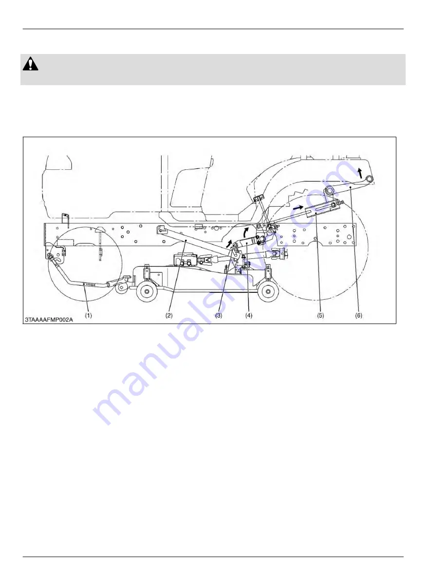
2. Structure of lifting mechanism of mower
CAUTION
• Never operate mower in transport position.
The lifting of mower is performed by the hydraulic system installed on the tractor.
The mower should be kept lift when traveling. When the position control lever is moved to
LIFT
position, the lift arm
(6) is lifted up by the oil pressure of hydraulic system, and the rear lift link (L.H.) (5) is pulled rearward.
Therefore, rear lift links (4), (5) rotate and the mower is lifted by the lift links (3) and rear links (2).
As this link system is a parallel linkage, the mower can be kept parallel at every position.
(1) Front link
(2) Rear link
(3) Lift link
(4) Rear lift link (R.H.)
(5) Rear lift link (L.H.)
(6) Lift arm
9. MOWER
MECHANISM
2. Structure of lifting mechanism of mower
9-2
BX1880,BX2380,BX2680,RCK60B-23BX,RCK54-23BX,RCK48-18BX,RCK60D-26BX,RCK54D-26BX
KiSC issued 03, 2019 A
Summary of Contents for ,RCK60B-23BX
Page 19: ...1 INFORMATION KiSC issued 03 2019 A ...
Page 42: ...2 GENERAL KiSC issued 03 2019 A ...
Page 111: ...3 ENGINE KiSC issued 03 2019 A ...
Page 190: ...4 TRANSAXLE KiSC issued 03 2019 A ...
Page 255: ...5 FRONT AXLE KiSC issued 03 2019 A ...
Page 274: ...6 STEERING KiSC issued 03 2019 A ...
Page 291: ...7 HYDRAULIC SYSTEM KiSC issued 03 2019 A ...
Page 344: ...8 ELECTRICAL SYSTEM KiSC issued 03 2019 A ...
Page 399: ...9 MOWER KiSC issued 03 2019 A ...


