2. Check length (L) and make sure it is set at the
factory specification.
Length (L) from
rear lock nut to
from end of front
link
Factory specifi-
cation
47 mm
1.85 in.
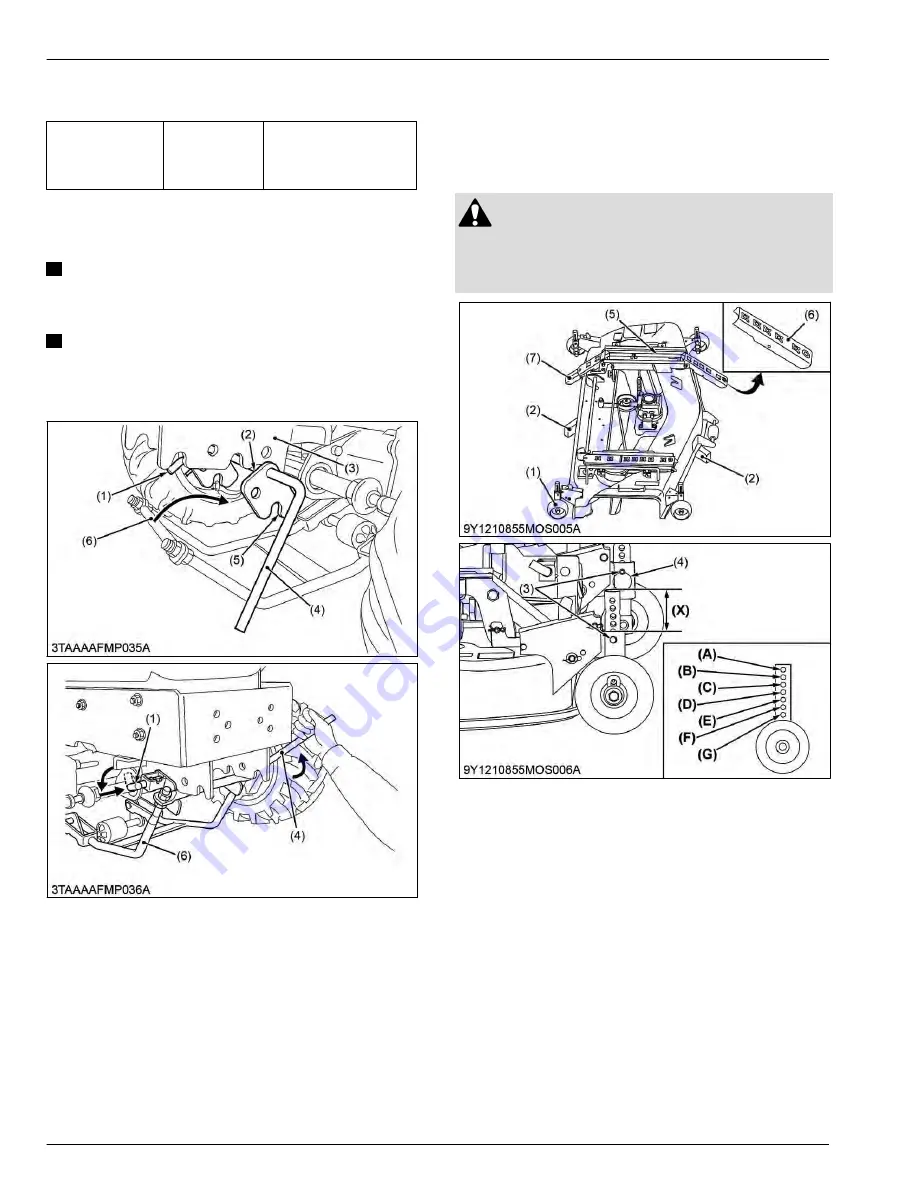
4.6 Mounting front link
IMPORTANT
• Check that the front lever is locked securely
with the L pin.
NOTE
• When hooking the front link to the lever
fulcrum, normal position of the lever fulcrum
groove is open to downward.
(1) L pin
(2) Lever fulcrum
(3) Front link bracket
(4) Front lever
(5) Lever fulcrum groove
(6) Front link
1. Position the front lever to the front link bracket.
2. Pull and lock the L pin. Then lower the front lever.
3. Hook the front link to the lever fulcrum, and lift the
front lever.
4. Release the L pin to lock the front lever.
5. Setting up mower
[RCK54D-26BX and
RCK60D-26BX]
5.1 Assembling mower
DANGER
To avoid serious injury or death:
• Do not operate the mower without the discharge
deflector properly in position.
(1) Anti-scalp roller
(2) Block
(3) Clevis pin
(4) Circlip
(5) F spring
(6) Ramp F
(7) Ramp R
1. Place the mower on blocks as illustrated.
2. Attach all the anti-scalp rollers to the arms of the
deck. Put clevis pins from outside and circlips inside
in the
F
position. 4.5 holes (X) must be visible.
9. MOWER
SERVICING
4. Setting up mower [RCK48-18BX, RCK54-23BX, and RCK60B-23BX]
9-10
BX1880,BX2380,BX2680,RCK60B-23BX,RCK54-23BX,RCK48-18BX,RCK60D-26BX,RCK54D-26BX
KiSC issued 03, 2019 A
Summary of Contents for ,RCK60B-23BX
Page 19: ...1 INFORMATION KiSC issued 03 2019 A ...
Page 42: ...2 GENERAL KiSC issued 03 2019 A ...
Page 111: ...3 ENGINE KiSC issued 03 2019 A ...
Page 190: ...4 TRANSAXLE KiSC issued 03 2019 A ...
Page 255: ...5 FRONT AXLE KiSC issued 03 2019 A ...
Page 274: ...6 STEERING KiSC issued 03 2019 A ...
Page 291: ...7 HYDRAULIC SYSTEM KiSC issued 03 2019 A ...
Page 344: ...8 ELECTRICAL SYSTEM KiSC issued 03 2019 A ...
Page 399: ...9 MOWER KiSC issued 03 2019 A ...


