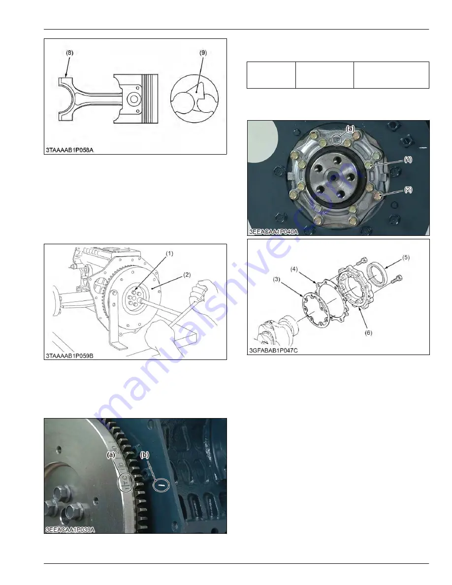
(8) Mark
(9) Fan-shaped concave
5.2.4 Flywheel and crankshaft
5.2.4.1 Removing flywheel
1. Secure the flywheel to keep it from turning, using a
flywheel stopper.
2. Remove all flywheel screws (1) and then remove
the flywheel (2).
(1) Flywheel screw
(2) Flywheel
(When reassembling)
• Align the
[1TC]
mark (a) on the outer surface of the
flywheel horizontally with the alignment mark (b) on
the rear end plate. Now fit the flywheel in position.
(a)
[1TC]
mark
(b) Alignment mark
• Apply engine oil to the threads and the undercut
surface of the flywheel screw and fit the screw.
Tightening tor-
que
Flywheel screw
54 to 58 N
⋅
m
5.5 to 6.0 kgf
⋅
m
40 to 43 lbf
⋅
ft
5.2.4.2 Removing bearing case cover
(1) Bearing case cover mount-
ing screw (Inside)
(2) Bearing case cover mount-
ing screw (Outside)
(3) Bearing case gasket
(4) Bearing case cover gasket
(5) Oil seal
(6) Bearing case cover
(a) Top mark
[UP]
1. Remove the bearing case cover mounting screws.
2. Remove the bearing case cover (6).
(When reassembling)
• Fit the bearing case gasket (3) and the bearing
case cover gasket (4) with correct directions.
SERVICING
5. Disassembling and assembling
3. ENGINE
BX1880,BX2380,BX2680,RCK60B-23BX,RCK54-23BX,RCK48-18BX,RCK60D-26BX,RCK54D-26BX
3-53
KiSC issued 03, 2019 A
Summary of Contents for ,RCK60B-23BX
Page 19: ...1 INFORMATION KiSC issued 03 2019 A ...
Page 42: ...2 GENERAL KiSC issued 03 2019 A ...
Page 111: ...3 ENGINE KiSC issued 03 2019 A ...
Page 190: ...4 TRANSAXLE KiSC issued 03 2019 A ...
Page 255: ...5 FRONT AXLE KiSC issued 03 2019 A ...
Page 274: ...6 STEERING KiSC issued 03 2019 A ...
Page 291: ...7 HYDRAULIC SYSTEM KiSC issued 03 2019 A ...
Page 344: ...8 ELECTRICAL SYSTEM KiSC issued 03 2019 A ...
Page 399: ...9 MOWER KiSC issued 03 2019 A ...


