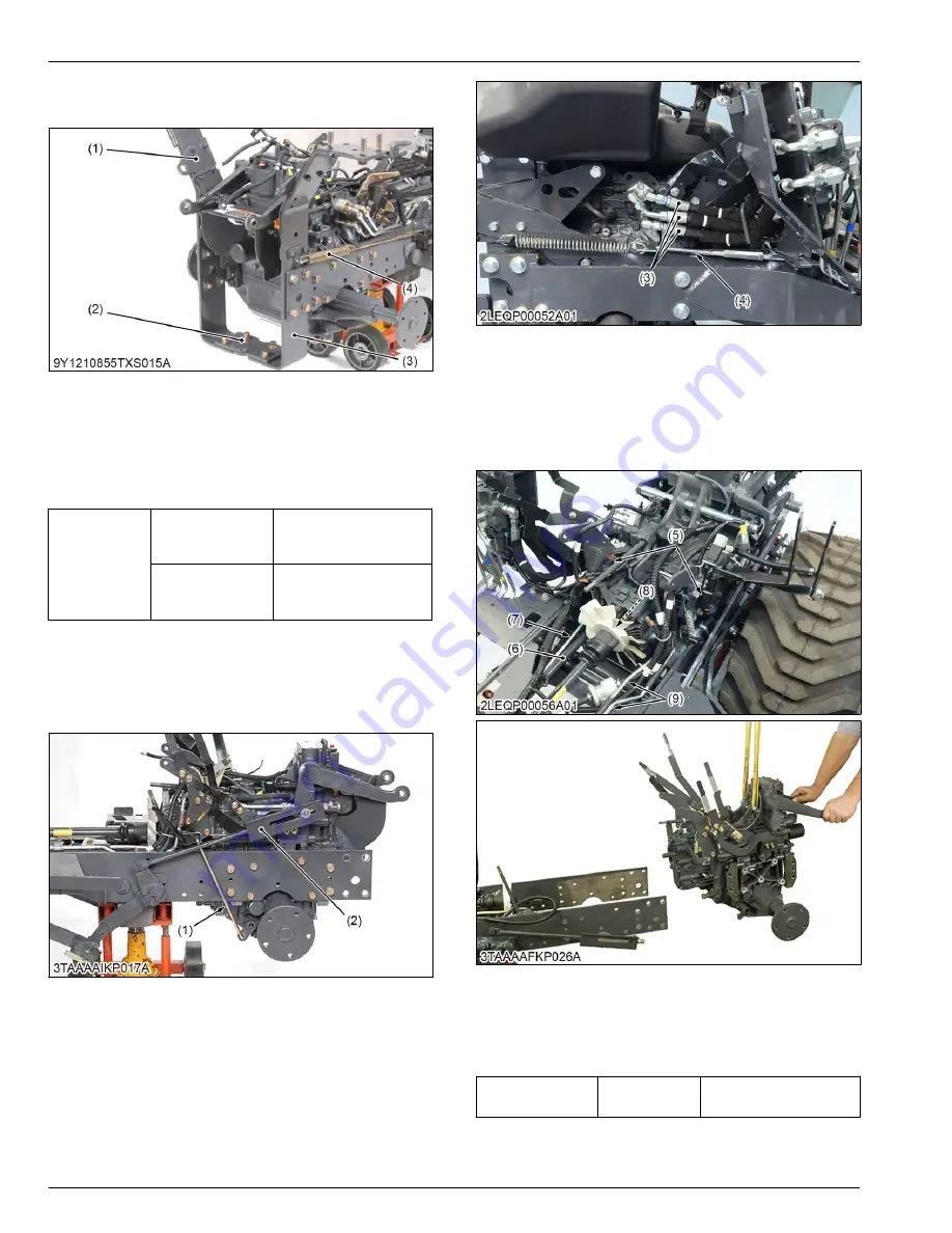
2. Remove the parking brake return spring (4) and the
fender brackets (1), (3).
(1) Fender bracket L.H.
(2) Hitch plate
(3) Fender bracket R.H.
(4) Return spring
(When reassembling)
• Do not firmly tighten all screws, bolts and nuts until
most components are attached.
Tightening tor-
que
Hitch plate mount-
ing bolt and nut
(M14)
124 to 147 N
⋅
m
12.6 to 15.0 kgf
⋅
m
91.2 to 108 lbf
⋅
ft
Fender bracket
mounting bolt and
nut (M14)
124 to 147 N
⋅
m
12.6 to 15.0 kgf
⋅
m
91.2 to 108 lbf
⋅
ft
5.1.12 Removing transaxle assembly
1. Remove the differential lock rod (1) and disconnect
the mower link (2).
(1) Differential lock rod
(2) Mower link
2. Remove the brake rod (4).
3. Disconnect the hoses (3). (If equipped.)
(3) Hoses
(4) Brake rod
4. Disconnect the connectors (5).
5. Remove the rear coupling mounting bolt (8).
6. Disconnect the power steering pipes (9) from the
transaxle.
7. Remove the speed control rod (7).
(5) Connector
(6) Front wheel drive shaft
(7) Speed control rod
(8) Rear coupling mounting bolt
(9) Power steering pipe
8. Remove the wire harness clamps.
9. Remove the frame brackets (10).
Speed control rod
length (7)
Reference val-
ue
373 mm
14.7 in.
4. TRANSAXLE
SERVICING
5. Disassembling and assembling
4-40
BX1880,BX2380,BX2680,RCK60B-23BX,RCK54-23BX,RCK48-18BX,RCK60D-26BX,RCK54D-26BX
KiSC issued 03, 2019 A
Summary of Contents for ,RCK60B-23BX
Page 19: ...1 INFORMATION KiSC issued 03 2019 A ...
Page 42: ...2 GENERAL KiSC issued 03 2019 A ...
Page 111: ...3 ENGINE KiSC issued 03 2019 A ...
Page 190: ...4 TRANSAXLE KiSC issued 03 2019 A ...
Page 255: ...5 FRONT AXLE KiSC issued 03 2019 A ...
Page 274: ...6 STEERING KiSC issued 03 2019 A ...
Page 291: ...7 HYDRAULIC SYSTEM KiSC issued 03 2019 A ...
Page 344: ...8 ELECTRICAL SYSTEM KiSC issued 03 2019 A ...
Page 399: ...9 MOWER KiSC issued 03 2019 A ...


