5. Remove the neutral adjuster (5) and the neutral arm
(3).
6. Remove the trunnion arm (6).
(When reassembling)
• Adjust the HST neutral position. Refer to "Checking
and adjusting" section.
5.3 Hydraulic cylinder
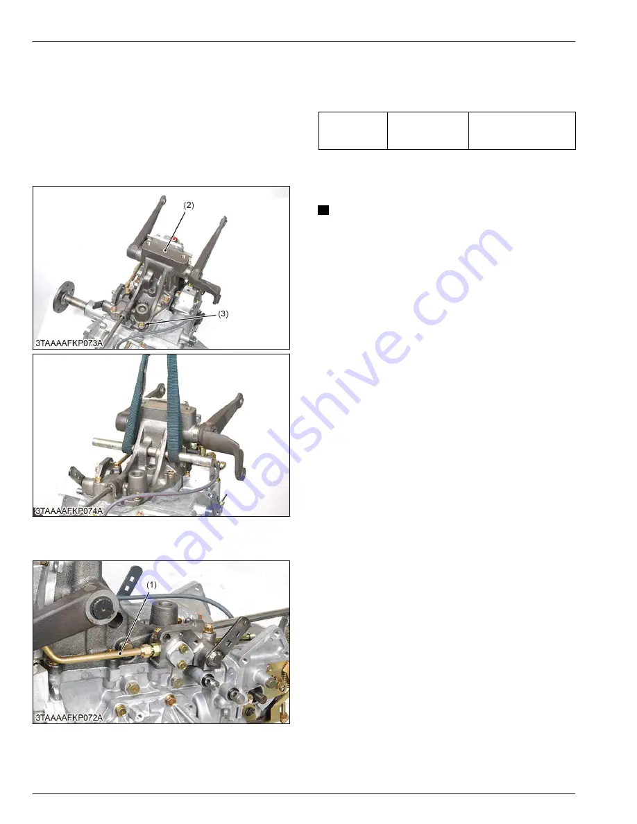
5.3.1 Removing hydraulic cylinder
(2) Hydraulic cylinder
(3) Bolt
1. Disconnect the delivery pipe (1).
(1) Delivery pipe
2. Remove the hydraulic cylinder mounting bolts (3).
3. Remove the hydraulic cylinder (2).
(When reassembling)
• Apply liquid gasket (Three Bond 1208D or
equivalent) to the joint surface of the transaxle case
to the hydraulic cylinder.
Tightening tor-
que
Hydraulic cylinder
mounting bolt
40 to 44 N
⋅
m
4.0 to 4.5 kgf
⋅
m
29 to 32 lbf
⋅
ft
5.4 Transaxle shafts
5.4.1 Removing transaxle case front cover
NOTE
• Before removing the transaxle case front cover
(4), remove the 4WD detent bolt (1), the detent
spring (2) and the detent ball (3) from the
transaxle case front cover (4).
• Remove the circlip (5) from the HST pump shaft
(PTO shaft) from the HST pump shaft (6) and the
HST motor shaft securely.
4. TRANSAXLE
SERVICING
5. Disassembling and assembling
4-48
BX1880,BX2380,BX2680,RCK60B-23BX,RCK54-23BX,RCK48-18BX,RCK60D-26BX,RCK54D-26BX
KiSC issued 03, 2019 A
Summary of Contents for ,RCK60B-23BX
Page 19: ...1 INFORMATION KiSC issued 03 2019 A ...
Page 42: ...2 GENERAL KiSC issued 03 2019 A ...
Page 111: ...3 ENGINE KiSC issued 03 2019 A ...
Page 190: ...4 TRANSAXLE KiSC issued 03 2019 A ...
Page 255: ...5 FRONT AXLE KiSC issued 03 2019 A ...
Page 274: ...6 STEERING KiSC issued 03 2019 A ...
Page 291: ...7 HYDRAULIC SYSTEM KiSC issued 03 2019 A ...
Page 344: ...8 ELECTRICAL SYSTEM KiSC issued 03 2019 A ...
Page 399: ...9 MOWER KiSC issued 03 2019 A ...


