6. Remove the differential pinions (12), (16), the
differential pinion washers (13), (17), differential
side gears (9), (14) and the differential side gear
washers (10), (15).
(When reassembling)
• Install the differential pinion and differential gear,
aligning the parting marks.
• Lock the differential pinion shaft (8) by setting the
key (11).
Tightening tor-
que
66T final gear
mounting bolt
61 to 70 N
⋅
m
6.2 to 7.2 kgf
⋅
m
45 to 52 lbf
⋅
ft
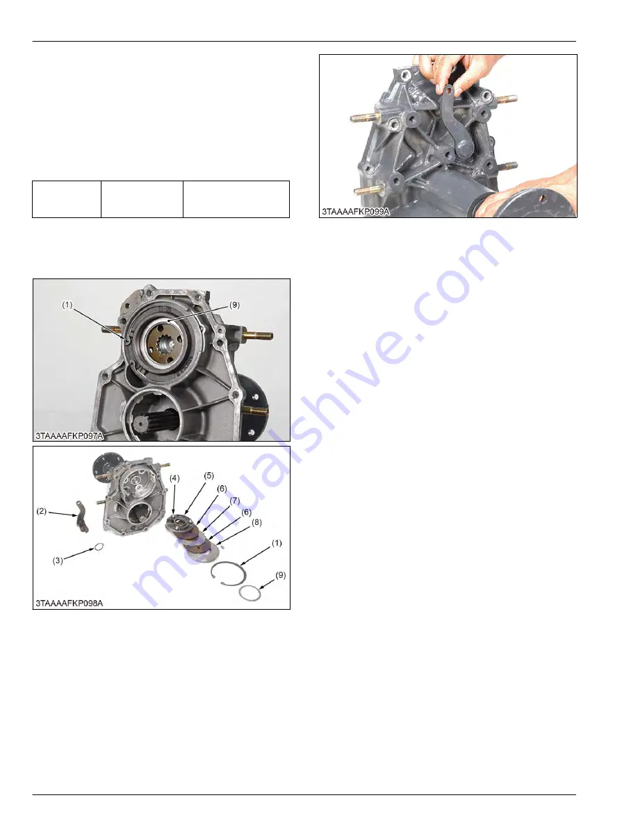
5.4.7 Removing rear axle case, R.H. and
brake
(1) Internal circlip
(2) Brake cam lever
(3) External circlip
(4) Steel ball
(5) Actuator
(6) Brake disc
(7) Friction plate
(8) Bearing holder
(9) Shim
1. Remove the internal circlip (1).
2. Remove the shim (9), the bearing holder (8) and the
other brake parts from the brake case.
(When reassembling)
• Apply grease to the steel balls.
• Be careful not to damage the O-ring on the brake
cam lever.
• Check that the brake cam lever moves smoothly.
4. TRANSAXLE
SERVICING
5. Disassembling and assembling
4-54
BX1880,BX2380,BX2680,RCK60B-23BX,RCK54-23BX,RCK48-18BX,RCK60D-26BX,RCK54D-26BX
KiSC issued 03, 2019 A
Summary of Contents for ,RCK60B-23BX
Page 19: ...1 INFORMATION KiSC issued 03 2019 A ...
Page 42: ...2 GENERAL KiSC issued 03 2019 A ...
Page 111: ...3 ENGINE KiSC issued 03 2019 A ...
Page 190: ...4 TRANSAXLE KiSC issued 03 2019 A ...
Page 255: ...5 FRONT AXLE KiSC issued 03 2019 A ...
Page 274: ...6 STEERING KiSC issued 03 2019 A ...
Page 291: ...7 HYDRAULIC SYSTEM KiSC issued 03 2019 A ...
Page 344: ...8 ELECTRICAL SYSTEM KiSC issued 03 2019 A ...
Page 399: ...9 MOWER KiSC issued 03 2019 A ...


