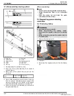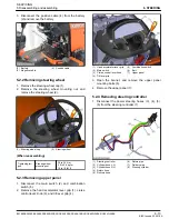
6.5 Checking backlash between
bevel pinion shaft and bevel gear
(1) Bevel gear
(2) Bevel pinion shaft
(3) Adjusting collar
(4) Adjusting collar
1. Put the wire of solder or plastigauge on the position
where the tooth proper contact of bevel pinion shaft.
Wire of solder
Factory specifi-
cation
Thickness
0.5 mm
0.02 in.
2. Fix the bevel gear and rotate the bevel pinon shaft
carefully.
3. Measure the backlash.
4. If the backlash is not within the factory
specifications, change the adjusting collar (3) and
(4).
Backlash between
bevel pinion shaft
and bevel gear
Factory specifi-
cation
0.1 to 0.3 mm
0.004 to 0.01 in.
(Reference)
Thickness of adjusting collars
(3), (4)
3.40 mm
0.134 in.
3.60 mm
0.142 in.
3.80 mm
0.150 in.
3.90 mm
0.154 in.
4.00 mm
0.157 in.
4.10 mm
0.161 in.
4.20 mm
0.165 in.
4.40 mm
0.173 in.
4.50 mm
0.177 in.
4.60 mm
0.181 in.
5. Adjust the backlash properly by repeating the above
procedures.
6.6 Checking backlash between 12T
bevel gear and 15T bevel gear
(1) 15T bevel gear
(2) 12T bevel gear
(3) Shim
1. Stick a strip of wire of solder or plastigauge to three
spots on the 15T bevel gear (1) with grease.
2. Fix the front axle case, bevel gear case and front
gear case.
3. Turn the axle.
4. Remove the bevel gear case from front axle case
and measure the backlash.
SERVICING
6. Servicing
5. FRONT AXLE
BX1880,BX2380,BX2680,RCK60B-23BX,RCK54-23BX,RCK48-18BX,RCK60D-26BX,RCK54D-26BX
5-17
KiSC issued 03, 2019 A
Summary of Contents for ,RCK60B-23BX
Page 19: ...1 INFORMATION KiSC issued 03 2019 A ...
Page 42: ...2 GENERAL KiSC issued 03 2019 A ...
Page 111: ...3 ENGINE KiSC issued 03 2019 A ...
Page 190: ...4 TRANSAXLE KiSC issued 03 2019 A ...
Page 255: ...5 FRONT AXLE KiSC issued 03 2019 A ...
Page 274: ...6 STEERING KiSC issued 03 2019 A ...
Page 291: ...7 HYDRAULIC SYSTEM KiSC issued 03 2019 A ...
Page 344: ...8 ELECTRICAL SYSTEM KiSC issued 03 2019 A ...
Page 399: ...9 MOWER KiSC issued 03 2019 A ...


