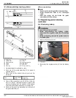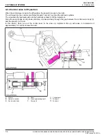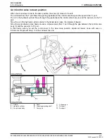
5.1.2 Disassembling steering cylinder
(1) Piston rod
(2) Cylinder tube
(3) Guide assembly
(4) Circlip
(5) Guide
(6) Seal ring
(7) Wiper ring
(8) O-ring
(9) Piston rod assembly
(10) Center piston
(A) Drill a hole.
(B) 5.25 mm (0.207 in.)
1. Carefully clamp the cylinder in a vise.
2. Push one of the guide assembly (3) to inside of
cylinder tube (2).
3. Drill a hole on the cylinder tube (2) just over the
circlip (4).
Hole
Factory specifi-
cation
2.5 mm dia.
0.098 in. dia.
4. Take a little screwdriver and lift off the circlip (4)
from its groove. Simultaneousness support this
action by pushing from the outside of the cylinder
tube with another little screwdriver or another tool.
5. Push out the piston rod assembly (9) and take off
the guide assembly (3).
(When reassembling)
NOTE
• Seals must be exchanged after disassembling.
• Apply transmission fluid to the exchanged
seals.
• Enter the piston rod and block the guide
assemblies with the circlips.
5.2 Separating power steering
controller
5.2.1 Removing battery
WARNING
To avoid serious injury or death:
• When disconnecting the battery cables,
disconnect the negative cable from the battery
first.
• When connecting, connect the positive cable to
the battery first.
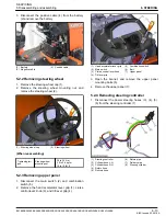
1. Remove the under panel (1).
(1) Under panel
2. Disconnect the negative cable (3) from the battery
(2).
6. STEERING
SERVICING
5. Disassembling and assembling
6-12
BX1880,BX2380,BX2680,RCK60B-23BX,RCK54-23BX,RCK48-18BX,RCK60D-26BX,RCK54D-26BX
KiSC issued 03, 2019 A
Summary of Contents for ,RCK60B-23BX
Page 19: ...1 INFORMATION KiSC issued 03 2019 A ...
Page 42: ...2 GENERAL KiSC issued 03 2019 A ...
Page 111: ...3 ENGINE KiSC issued 03 2019 A ...
Page 190: ...4 TRANSAXLE KiSC issued 03 2019 A ...
Page 255: ...5 FRONT AXLE KiSC issued 03 2019 A ...
Page 274: ...6 STEERING KiSC issued 03 2019 A ...
Page 291: ...7 HYDRAULIC SYSTEM KiSC issued 03 2019 A ...
Page 344: ...8 ELECTRICAL SYSTEM KiSC issued 03 2019 A ...
Page 399: ...9 MOWER KiSC issued 03 2019 A ...


