3. Hydraulic pump
3.1 Outline of hydraulic pump
This hydraulic pump is located on left side of
transmission.
Hydraulic pump is driven by the pump drive shaft in the
transmission case.
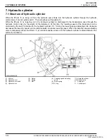
3.2 Structure of hydraulic pump
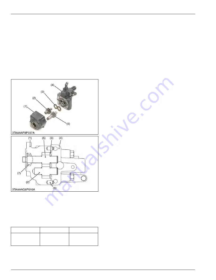
The hydraulic pump consists of the casing (1), cover
(4), side plate (3), and two spur gears (drive gear (5)
and driven gear (2)) that are in mesh.
(1) Casing
(2) Driven gear
(3) Side plate
(4) Cover
(5) Drive gear
(6) Pin
(7) Oil seal
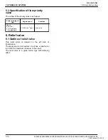
3.3 Specification of hydraulic pump
Maximum displacement of hydraulic pump is as follows.
Displacement
Engine speed
Condition
23.5 L/min.
6.2 U.S.gals/min.
5.2 Imp.gals/min.
At 3200 min
-1
(rpm)
At no load
4. Control valve
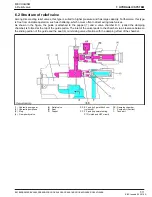
4.1 Outline of control valve
This position control valve is located under the
hydraulic cylinder.
This control valve is mechanically connected to the
position control lever.
Since the feedback rod is not equipped to the lift arm,
the neutral position adjustment is adjusted by
controlling the position control lever.
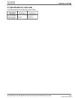
The control valve controls the oil flow forced from the
hydraulic pump and the oil returned back from the
hydraulic cylinder.
7. HYDRAULIC SYSTEM
MECHANISM
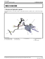
3. Hydraulic pump
7-4
BX1880,BX2380,BX2680,RCK60B-23BX,RCK54-23BX,RCK48-18BX,RCK60D-26BX,RCK54D-26BX
KiSC issued 03, 2019 A
Summary of Contents for ,RCK60B-23BX
Page 19: ...1 INFORMATION KiSC issued 03 2019 A ...
Page 42: ...2 GENERAL KiSC issued 03 2019 A ...
Page 111: ...3 ENGINE KiSC issued 03 2019 A ...
Page 190: ...4 TRANSAXLE KiSC issued 03 2019 A ...
Page 255: ...5 FRONT AXLE KiSC issued 03 2019 A ...
Page 274: ...6 STEERING KiSC issued 03 2019 A ...
Page 291: ...7 HYDRAULIC SYSTEM KiSC issued 03 2019 A ...
Page 344: ...8 ELECTRICAL SYSTEM KiSC issued 03 2019 A ...
Page 399: ...9 MOWER KiSC issued 03 2019 A ...


