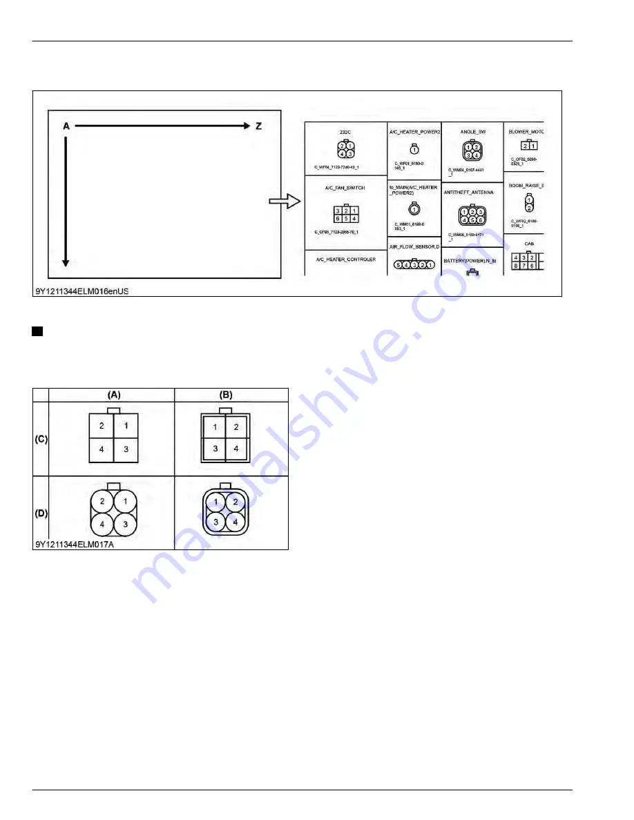
3.2 Layout of connector diagrams
Connector arrangement sequence
Depiction of connectors
NOTE
• In principle, the connector locking part is shown on the top side.
• Female connector terminal numbers start from 1 in the top right corner, looking at the connecting face.
• Male connector terminal numbers start from 1 in the top left corner.
(A) Female connector terminal
(B) Male connector terminal
(C) Not waterproof
(D) Waterproof
8. ELECTRICAL SYSTEM
MECHANISM
3. Reading electrical circuit diagrams
8-6
BX1880,BX2380,BX2680,RCK60B-23BX,RCK54-23BX,RCK48-18BX,RCK60D-26BX,RCK54D-26BX
KiSC issued 03, 2019 A
Summary of Contents for ,RCK60B-23BX
Page 19: ...1 INFORMATION KiSC issued 03 2019 A ...
Page 42: ...2 GENERAL KiSC issued 03 2019 A ...
Page 111: ...3 ENGINE KiSC issued 03 2019 A ...
Page 190: ...4 TRANSAXLE KiSC issued 03 2019 A ...
Page 255: ...5 FRONT AXLE KiSC issued 03 2019 A ...
Page 274: ...6 STEERING KiSC issued 03 2019 A ...
Page 291: ...7 HYDRAULIC SYSTEM KiSC issued 03 2019 A ...
Page 344: ...8 ELECTRICAL SYSTEM KiSC issued 03 2019 A ...
Page 399: ...9 MOWER KiSC issued 03 2019 A ...


