3. Turn the main switch key to the
START
position,
and measure the voltage with a voltmeter between
the lead terminal and the chassis.
4. If the voltage at either position differs from the
battery voltage, the wiring harness or main switch is
damaged.
Voltage (Lead ter-
minal - Chassis)
Main switch
key at
PRE-
HEAT
Approx. battery voltage
Main switch
key at
START
Approx. battery voltage
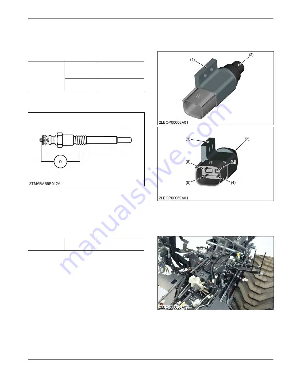
4.4.2 Checking glow plug continuity
1. Disconnect the lead from the glow plugs.
2. Measure the resistance with an ohmmeter between
the glow plug terminal and the chassis.
3. If 0 ohm is indicated, the screw at the tip of the glow
plug and the housing are short-circuited.
4. If the factory specification is not indicated, the glow
plug is damaged.
Glow plug
Factory specifi-
cation
Approx. 0.9 Ω
4.5 Safety switch
4.5.1 Checking PTO shift lever switch
continuity
(1) PTO shift lever switch
(2) Plunger
(3) 4 terminal
(4) 8 terminal
(5) 5 terminal
(6) 1 terminal
1. Remove the left rear wheel.
2. Remove the PTO shift lever switch (1).
(1) PTO shift lever switch
3. Measure the resistance with an ohmmeter across
the switch terminals.
SERVICING
4. Checking and adjusting
8. ELECTRICAL SYSTEM
BX1880,BX2380,BX2680,RCK60B-23BX,RCK54-23BX,RCK48-18BX,RCK60D-26BX,RCK54D-26BX
8-33
KiSC issued 03, 2019 A
Summary of Contents for ,RCK60B-23BX
Page 19: ...1 INFORMATION KiSC issued 03 2019 A ...
Page 42: ...2 GENERAL KiSC issued 03 2019 A ...
Page 111: ...3 ENGINE KiSC issued 03 2019 A ...
Page 190: ...4 TRANSAXLE KiSC issued 03 2019 A ...
Page 255: ...5 FRONT AXLE KiSC issued 03 2019 A ...
Page 274: ...6 STEERING KiSC issued 03 2019 A ...
Page 291: ...7 HYDRAULIC SYSTEM KiSC issued 03 2019 A ...
Page 344: ...8 ELECTRICAL SYSTEM KiSC issued 03 2019 A ...
Page 399: ...9 MOWER KiSC issued 03 2019 A ...


