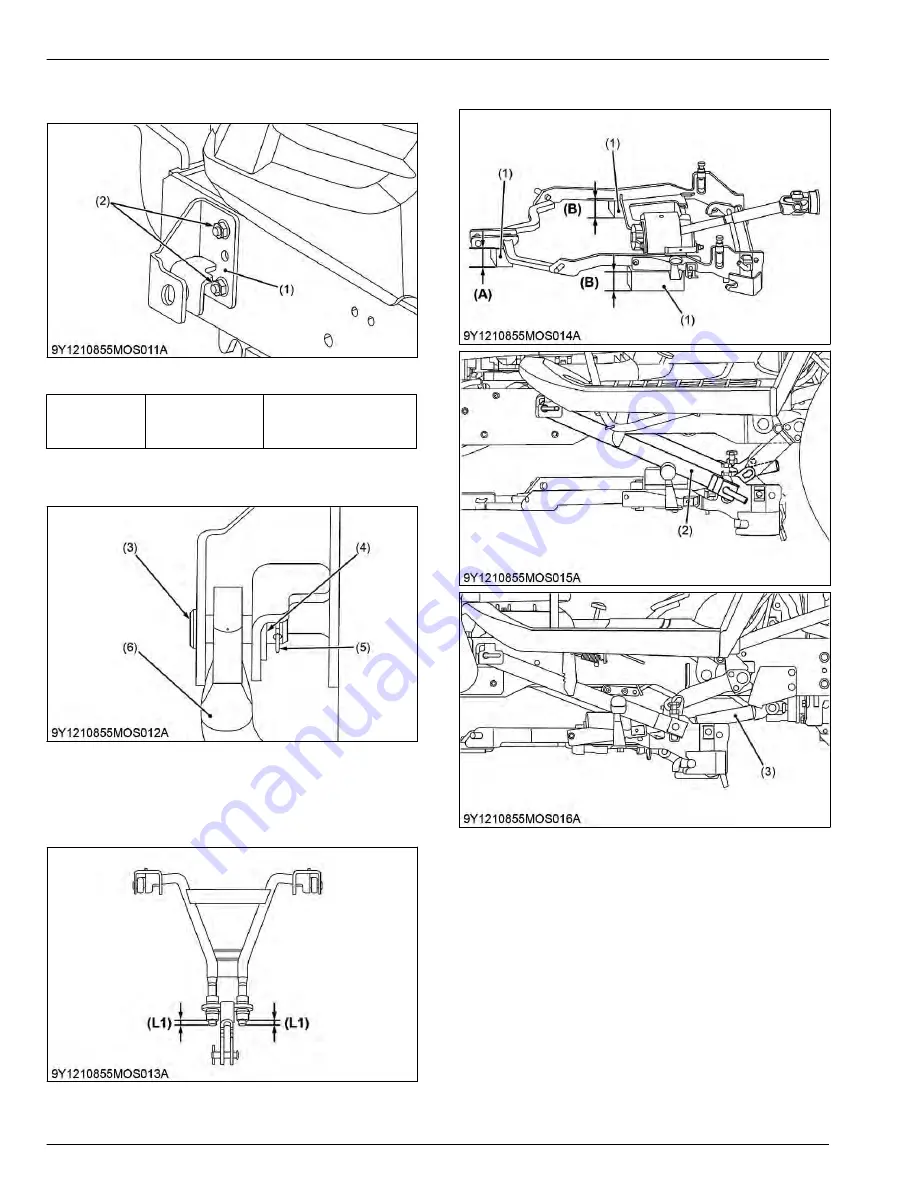
2. Attach the stay link (1) with the nut (2) on the tractor
front frame.
(1) Stay link
(2) Nut
Tightening tor-
que
Stay link nut
43.3 to 50.3 N
⋅
m
4.4 to 5.1 kgf
⋅
m
32 to 37 lbf
⋅
ft
3. Attach the front link (6) to the stay link (1) with joint
pin (3), washer (4) and snap pin (5).
(3) Joint pin
(4) Washer
(5) Snap pin
(6) Front link
4. Before attaching the mower links, adjust lengths
(L1) to 22 mm.
(L1) 22 mm
5.4 Mounting frame link
(1) Block
(2) Link arm
(3) Universal joint
(A) 160 mm (6.3 in.)
(B) 120 mm (4.7 in.)
1. Place blocks below the frame link if one person
does the setting. Heights of blocks are
recommended value for attaching.
2. Start engine. Set the cutting height to 0 mm (0 in.)
and lower the frame link. Then stop the engine.
3. Attach the frame link to the link arm.
4. Joint the front link and frame link with joint pin and
circlip.
5. Attach the universal joint to tractor.
9. MOWER
SERVICING
5. Setting up mower [RCK54D-26BX and RCK60D-26BX]
9-12
BX1880,BX2380,BX2680,RCK60B-23BX,RCK54-23BX,RCK48-18BX,RCK60D-26BX,RCK54D-26BX
KiSC issued 03, 2019 A
Summary of Contents for ,RCK60B-23BX
Page 19: ...1 INFORMATION KiSC issued 03 2019 A ...
Page 42: ...2 GENERAL KiSC issued 03 2019 A ...
Page 111: ...3 ENGINE KiSC issued 03 2019 A ...
Page 190: ...4 TRANSAXLE KiSC issued 03 2019 A ...
Page 255: ...5 FRONT AXLE KiSC issued 03 2019 A ...
Page 274: ...6 STEERING KiSC issued 03 2019 A ...
Page 291: ...7 HYDRAULIC SYSTEM KiSC issued 03 2019 A ...
Page 344: ...8 ELECTRICAL SYSTEM KiSC issued 03 2019 A ...
Page 399: ...9 MOWER KiSC issued 03 2019 A ...


