p. 15 of 18
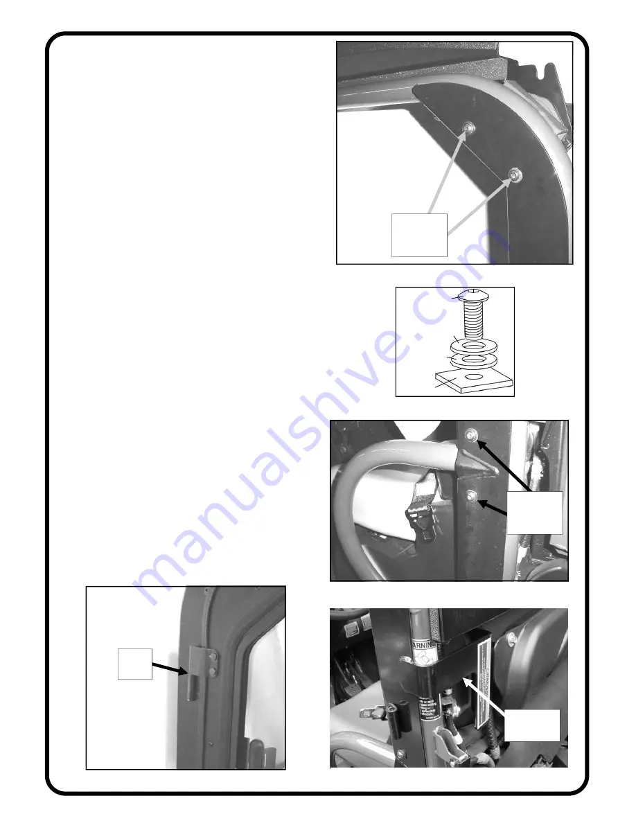
5.4 Install a door hinge plate to the outside of the rear
ROPS tubing as shown in fig. 5.4. Use the following
hardware: two 5/16-18 x 1” long button head bolts, four
steel flat washers (5/16”), four plastic washers (3/8”),
and two locknuts (5/16-18). Locknuts to be on the inside
of the cab. See fig. 5.4.1 for placement of plastic wash-
ers. Leave bolts loose.
5.5 Per fig. 5.5, fasten the lower portion of the door
hinge plate to the hip restraint tube using the ROPS U-
clamps provided and the following hardware: two 5/16-
18 x 1” long button head bolts, four steel flat washers,
four plastic washers (3/8”), and two locknuts (5/16-18).
Locknuts to be on the inside of the cab. Be sure to orient
the U-clamp so that the angle of the clamp is aligned
with the angle of the ROPS hip restraint tube that it fas-
tens to. See fig. 5.4.1 for placement of plastic washers.
Leave bolts loose.
NOTICE: The Restriction Plate on the Door Hinge Plate
per fig. 5.5.1 (Driver’s side only) is designed to prevent
assembly onto the RTV 500. Do not remove or alter this
plate.
5.6 Align rear edge of door hinge plate parallel with
vertical ROPS tube. Tighten all four bolts.
5.7 Repeat for passenger’s side.
5.8 Open the front portion of the sliding window on
each door to keep from being locked out of the cab.
5.9 Apply grease to the factory installed pin hinges
and install the doors by lining up the pin hinges on the
door with the hinge sleeves on the door hinge plate.
Work the doors back and forth until they are completely
seated on the pin hinges.
5.10 Close the door fully and determine if the door is
approximately centered to the ROPS tubing. If necessary,
loosen the pin hinges on the door and adjust as necessary.
Hinge holes are oversized for adjustment in all direc-
tions. Re-tighten the pin hinge bolts.
Fig. 5.4 (view of driver’s side)
button head
bolts and
washers
Fig. 5.5 (view of driver’s side)
button head
bolts and
washers
Fig. 5.9 (view of passenger’s side)
apply
grease
Fastener
Cab Surface
Steel Washer
Plastic Washer
Fig. 5.4.1 (placement of plastic washers)
Restriction
plate
Fig. 5.5.1 (view of driver’s side)
Summary of Contents for RTV 400 CAB
Page 6: ...P 6 OF 18 PARTS LIST V4310 77700 V4310 RTV 400 MOUNT KIT ...
Page 9: ...P 9 OF 18 V4368 77700 V4368 RTV 400 WINDSHIELD KIT PARTS LIST ...
Page 11: ...V4428 77700 V4428 RTV 400 REAR PANEL KIT PARTS LIST P 11 OF 18 ...
Page 13: ...V4312 77700 V4312 RTV 400 ROOF KIT PARTS LIST P 13 OF 18 INSIDE VIEW OF ROOF ASSEMBLY ...
Page 17: ...PARTS LIST V4429 77700 V4429 RTV 400 DOOR KIT P 17 OF 18 ...


