WSM U15-3
II-175
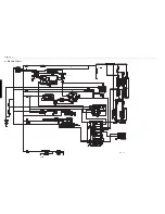
2 Route of Electric Wiring (Engine Rear)
(1) Theft-proof key setting terminal
(2) Key setting connector
(3) Slow-blow fuse
(4) Direct the fuse box so that the slot comes to the right.
(5) Pass the battery cord, dozer cable and wire harness to the theft-proof unit through the hole of the vertical
rib.
(6) Insert RA221-5322
'
battery cord (Plus) into the threaded hole from the front side of the mount.
(7) Facing directly above
(8) Clamp the wire harness and the rubber cap after assembling the terminal.
(9) Pass the power cord through the upper hole.
(10)Pass the minus cord through the lower hole.
(11)The minus terminal should be directed abeam at the machine front.
(12)Pass the plus power cord behind the arch.
(1)
(3)
(2)
(5)
(6)
(7)
(8)
(4)
(9)
(10)
(11)
(12)
Summary of Contents for u15-3
Page 1: ...WORKSHOP MANUAL KUBOTA EXCAVATOR U15 3 Code No 97899 61270...
Page 3: ...ss I Product engineering section II Service engineering section CONTENTS...
Page 4: ......
Page 6: ...WSM U15 3 I 2...
Page 20: ...WSM U15 3 I 16...
Page 65: ...WSM U15 3 II 45 b Performance curves...
Page 72: ...WSM U15 3 II 52 g Cooling system 1 Structure Hole Clamp Cap Through Cap pressure...
Page 83: ...WSM U15 3 II 63 3 Control Valve 2 Front Rear...
Page 88: ...WSM U15 3 II 68 7 Inner sectional view Tightening torque T 13 7 14 7 N m T 1 4 1 5 kgf m...
Page 130: ...WSM U15 3 II 110...
Page 132: ...WSM U15 3 II 112 n Hydraulic circuit diagram...
Page 170: ...WSM U15 3 II 150 8 Auto release and auto glow circuit combined Glow plug Glow lamp...
Page 200: ...WSM U15 3 II 180...
Page 209: ...ss Conversion Tables...
Page 210: ......
Page 211: ......


